
Page 115 - Wastewater Solids Incineration Systems
P. 115
84 Wastewater Solids Incineration Systems
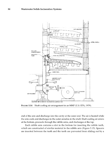
FIGURE 5.14 Shaft cooling air arrangement in an MHF (U.S. EPA, 1979).
end of the arm and discharge into the cavity at the outer end. The air is heated while
the arm cools and discharges to the outer annulus in the shaft. Shaft cooling air enters
at the bottom, proceeds through the rabble arms, and discharges at the top.
Each rabble arm contains a slot in the bottom for inserting the rabble teeth,
which are constructed of similar material to the rabble arm (Figure 5.15). Spacers
are inserted between the teeth and the teeth are prevented from sliding out by a