
Page 256 - Wastewater Solids Incineration Systems
P. 256
218 Wastewater Solids Incineration Systems
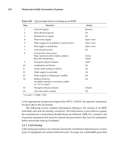
TABLE 10.1 Typical steps before warming up an MHF.
Step Function Action
1. Lockout/tagout Remove
2. Main electrical power On
3. Instrument air supply On
4. Plant water supply Open valve
5. Water supply to air pollution control system Open valve
6. Fuel supply to incinerator Open valve
7. Control panel power On
8. Annunciator alarm panel
Paper and ink in all recorders, printers Check
Recorder functioning Check
9. Emergency bypass damper Open
10. Combustion air blower On
11. Center shaft cooling air blower On
12. Water supply to precooler On
13. Water supply to exhaust gas scrubber On
14. Induced draft fan On
(set draft controller to maintain a draft
of 0.1 in water*)
15. Emergency bypass damper Closed
16. Ash conveyance system On
* in water 0.2488 kPa.
to the appropriate temperature higher than 593°C (1100°F), the operator introduces
the feed cake to the incinerator.
The following section contains information relating to the startup of an MHF
from both cold and hot standby conditions. This information is provided as a guide;
the manufacturer’s instructions should always be followed. Table 10.1 contains a list
of general equipment that must be started and procedures that must be performed
before incinerator heat-up is initiated.
2.2.1 Cold Startup
Cold startup procedures vary between incinerator installations depending on various
types of equipment and system interlocks used. To purge any combustible gases that