
Page 229 - Water Engineering Hydraulics, Distribution and Treatment
P. 229
207
Problems/Questions
50 L/s
d (in.)
Pipe
Point
L (ft)
Elevation (ft)
B
30 L/s
55
F
105
6
500
DE
L/s
500
6
100
EF
G
R
C
Water
115 L/s
H
E
A
105
2,000
14
DG
reservoir
109
EH
2,000
I
6
FI
2,000
d
FI
D
500
GH
12
25 L/s
HI
12
400
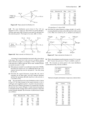
Figure 6.25 Water network for Problem 6.9.
All pipes have a C value of 100.
6.10
The water distribution system shown in Fig. 6.26 was
designed to serve a small city. Water flows by gravity through a (a) Determine the required diameters of pipes AB, BC, CF, and FG,
assuming that the maximum, allowable head loss in the system
400 mm water main (ABC) from the water reservoir and feeds into is 2‰. (Hint: Use sections aa, bb, cc, and dd in your analysis.)
the network at point C. The length of the main, ABC, is 10 km.
100 gpm b 200 gpm 2300 gpm
10 L/s 10 L/s 10 L/s c a
G D A
D E F d
a
10 L/s 20 L/s 100 gpm 300 gpm 200 gpm
Water A B G 35 L/s B
reservoir C K H E
J I H
C b
I d F c
10 L/s 10 L/s 10 L/s
900 gpm 150 gpm 350 gpm
Figure 6.26 Water network for Problem 6.10.
Figure 6.27 Water network for Problem 6.11.
At present, the water demand has increased to the values shown
(b) What is the minimum possible pressure at point I? Is it accept-
in the figure. The water level in the reservoir is at 400 m, and the
able? Assume that a pressure of 30 psi is available at point A.
whole network is located at an elevation of 340 m. Each quadrant
in the network is 1,000 m long and 500 m wide. Assume all pipes 6.12 The elevations at various points in the water distribution
are ductile iron with C = 100. system shown in Fig. 6.28 are as follows:
(a) If the pressure at point C is not allowed to drop below 300 kPa,
determine the required size of an additional ductile pipe to be A, B, and D 528.5 m
installed between the reservoir and point B, 7 km away along C, E, and G 530.0 m
the line AC. F and H 531.5 m
(b) Determine the required diameters of pipes DE, CK, and JI, I 532.5 m
assuming that all three pipes will have identical diameters
and that the maximum allowable head loss in the network is
3 m/1,000 m (3‰). The known lengths and diameters of pipes are as shown below:
6.11 The main pipe layout of a water distribution system is shown
in Fig. 6.27. The water demand for the system (domestic + fire) is
2,300 gpm and is supplied at point A. At point I, the most unfavor- Pipe d (mm) L (m)
able as far as loss of head is concerned, it is assumed that a fire plus
AB d 200
the domestic flow requires 900 gpm. At other intersection points it AB
BC 250 200
is estimated that the amounts shown will be required to satisfy the
DE 200 200
normal domestic demand. The elevations at intersections of mains
EF 150 200
are as follows:
GH 300 200
HI d HI 200
Point Elevation (ft) Pipe d (in.) L (ft) AD 400 500
BE 200 500
A 95 AB d 500
AB CF d 500
B 95 BC d 400 CF
BC DG d 600
C 100 BE 8 1,600 DG
EH 150 600
D 95 CF d CF 1,600 FI 200 600
E 100 AD 16 1,600