Page 231 - Water Engineering Hydraulics, Distribution and Treatment
P. 231

209
                                                                                                                  Problems/Questions
                                    fire flow is 12,200 L/min. The residual pressure in mains ABCDA
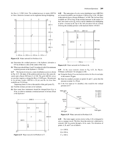
                                                                                      are located downhill at an elevation of 600 m (Fig. 6.34). All pipes
                                    is 4 bars. Domestic demand can be neglected during firefighting.
                                                                                      in the network have a Hazen–Williams C of 100. The fire hose lines
                                                                 3
                                                 1
                                                         2
                                                                                      available are 150 m long. If the residual pressure in the mains is 4
                                                                          B
                                        A
                                                                                      bars, how much water (Q in L/s) can be withdrawn for firefighting
                                                                                                        F
                                                                                      at point x located at the top of the hill (elevation 619 m) without
                                                                            225 m
                                                                                      lowering the residual pressure at the hydrants below 150 kPa?
                                       4
                                                                                               A
                                                                                                                            B
                                                                                                       150 mm
                                                                                                                200 mm
                                                                            225 m
                                                          X
                                                                                                           250 m
                                       5
                                                                            225 m     6.18  The main pipes of a city water distribution loop (ABCDA)
                                                                                                                            150 mm
                                                                                                   250 m
                                       6
                                                                                          750 m              X
                                                                            225 m
                                                                                                                            200 mm
                                        D                                 C
                                           225 m   225 m   225 m   225 m
                                    Figure 6.32 Water network for Problem 6.16.               D                             C
                                    (a) Determine the residual pressure at the hydrants (elevation =        750 m
                                       645 m) if there is a fire at the center of the loop.  Figure 6.34 Water network for Problem 6.18.
                                    (b) What sizes should lines 2 and 5 be replaced with if the minimum
                                       required pressure at the hydrants is 150 kPa?  6.19  In the water network shown in Fig. 6.35, the Hazen–
                                    6.17  The layout of a loop in a water distribution system is shown  Williams coefficient C for all pipes is 100.
                                    in Fig. 6.33. All pipes of the gridiron network have the same ele-  (a) Using the Hardy Cross method, determine the flow in each pipe
                                    vation and a Hazen–Williams C of 100. The grid ABCDA serves  to the nearest 20 gpm.
                                    an area that requires a design fire flow of 9,000 gpm. The pressure
                                                                                      (b) Find the residual pressures at points B and C, given that the
                                    in the primary feeders ABCDA is 30 psi, and the fire hose lines
                                                                                         pressure at point A is 50 psi.
                                    available are 410 ft long.
                                                                                      (c) If the flow input at A is doubled, what would be the residual
                                       Supposing there is a fire at the middle of the grid (point X),
                                                                                         pressure at C?
                                    (a) Find the residual pressure at the hydrants.
                                    (b) How many lines (minimum) should be changed from 8 in. to
                                       10 in. in order to maintain a residual pressure of at least 20 psi  1600 gpm A         Elevation
                                       at the hydrants?                                                                       A  100 ft
                                                                                                                              B  150 ft
                                                                                                         1500 ft              C  140 ft
                                                                                                            8 in
                                                       2400 ft                             500 ft
                                                                                           10 in
                                         A                              B
                                                                                                                            C
                                                                                              B
                                                     8 in      8 in
                                                                                                        1000 ft    10 in
                                                                                                                            1000 gpm
                                                                  8 in                   600 gpm
                                                                                         Figure 6.35 Water network for Problem 6.19.
                                                         X               2400 ft
                                                                                      6.20  The water supply system shown in Fig. 6.36 is designed to
                                              800 ft              8 in
                                                                                      serve a summer resort. The flow from the reservoir is delivered to
                                                                                      network ABC by gravity through a 14 in. main. The elevations of
                                                      800 ft                          points A, B, and C are as follows:
                                                                                        A = 100 ft;
                                         D                              C
                                                                                        B = 150 ft;
                                       Figure 6.33 Water network for Problem 6.17.      C = 140 ft.
   226   227   228   229   230   231   232   233   234   235   236