
Page 232 - Water Engineering Hydraulics, Distribution and Treatment
P. 232
210
Water Distribution Systems: Components, Design, and Operation
Chapter 6
(a) Find the flow in each pipe.
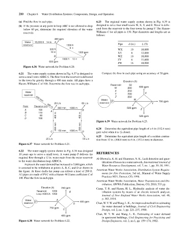
designed to serve four small towns W, X, Y, and Z. Water is deliv-
(b) If the pressure at any point in loop ABC is not allowed to drop
ered from the reservoir to the four towns by pump P. The Hazen–
below 60 psi, determine the required elevation of the water
Williams C for all pipes is 130. Pipe diameters and lengths are as
reservoir.
follows:
400 gpm
A
Water
10,000 ft 14 in
d (in.)
L (ft)
Pipe
reservoir
1500 ft
8 in
WX
500 ft
10,000
10
10 in
12,000
6
XY
10,000
B
WZ
10
C
11,000
6
ZY
600 gpm 1000 ft 10 in 1000 gpm 6.23 The regional water supply system shown in Fig. 6.39 is
PW 16 40,000
Figure 6.36 Water network for Problem 6.20.
6.21 The water supply system shown in Fig. 6.37 is designed to Compute the flow in each pipe using an accuracy of 20 gpm.
serve a small town ABDCA. The flow from the reservoir is delivered
to the town by gravity through a 400 mm main. All pipes have a
Elevation (ft)
Hazen–Williams C of 100. Determine the flow rate in each pipe.
Reservoir 50
W 200 600 gpm
X 250
Water X
reservoir Y 200
Z 250
Water W 700 gpm
400 mm
20 L/s 60 L/s reservoir P Y
Point Elevation (m) 400 m
300 mm 1600 m 500 gpm
A 100 A B Z
B 110
C 80 400 m 400 m 500 gpm
D 100
Figure 6.39 Water network for Problem 6.23.
200 mm 200 mm 6.24 Determine the equivalent pipe length of a 6 in (152.4 mm)
C 150 mm 1600 m D gate valve when it is ∕ 4 closed.
3
6.25 Determine the equivalent pipe length of a sudden contrac-
25 L/s 55 L/s tion from 12 in. (304.8 mm) to 6 in. (152.4 mm) in diameter.
Figure 6.37 Water network for Problem 6.21.
6.22 The water supply system shown in Fig. 6.38 was designed
10 years ago to serve a small town. A water pump P delivers the REFERENCES
required flow through a 12 in. water main from the water reservoir
Al-Dhowalia, K. H. and Shammas, N. K., Leak detection and quan-
to the water distribution loop ABDCA.
tification of losses in a water network, International Journal of
At present the water demand has increased to 2,000 gpm, which
Water Resources Development, vol. 7, no. 1, pp. 30–38, 1991.
is assumed to be withdrawn at points A, B, C, and D as shown in
American Water Works Association, Distribution System Require-
the figure. At these drafts the pump can deliver a head of 200 ft.
ments for Fire Protection, 3rd ed., Manual of Water Supply
All pipes are made of PVC with a Hazen–Williams coefficient C of
Practices M31, Denver, CO, 1998.
140. Find the flow in each pipe.
American Water Works Association, Water Transmission and Dis-
tribution, AWWA Publication, Denver, CO, 2010, 533 pp.
Elevation (ft) 250 gpm Camp, T. R. and Hazen, H. L., Hydraulic analysis of water dis-
Reservoir 1200 B tribution systems by means of an electric network analyzer,
Loop ABDCA 1250
Journal of New England Water Works Association, vol. 48,
p. 383, 1934.
Water A 600 gpm
reservoir P D Chan,W.Y.W.andWang,L.K.,Animprovedmethod forestimating
the water demand in buildings, Journal of Civil Engineering
750 gpm
C Design, vol. 2, no. 3, pp. 221–237, 1980.
Chan, W. Y. W. and Wang, L. K., Estimating of water demand
400 gpm
in apartment buildings, Civil Engineering for Practicing and
Figure 6.38 Water network for Problem 6.22. Design Engineers, vol. 2, no.1, pp. 159–174, 1982.