
Page 237 - Water Engineering Hydraulics, Distribution and Treatment
P. 237
215
7.4 Pipe Networks
An event or condition at one point in the system can
180
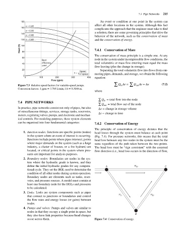
n = 0.95
160
complicates the approach that the engineer must take to find
n = 0.90
a solution, there are some governing principles that drive the
140
n = 0.85
behavior of the network, such as the conservation of mass
and the conservation of energy.
120 n = 0.80
Head (ft)
100
7.4.1 Conservation of Mass
80
The conservation of mass principle is a simple one. At any
60
node in the system under incompressible flow conditions, the
Best
total volumetric or mass flow entering must equal the mass
efficiency affect all other locations in the system. Although this fact
40
point
flow leaving (plus the change in storage).
20 Separating the total volumetric flow into flows from con-
n = Speed
0 Full speed necting pipes, demands, and storage, we obtain the following
0 100 200 300 400 equation:
Flow (gpm)
∑ ∑
Q Δt = Q Δt +Δs (7.2)
Figure 7.3 Relative speed factors for variable-speed pumps. in out
Conversion factors: 1 gpm = 3.785 L/min; 1 ft = 0.3048 m.
where
∑
Q = total flow into the node
in
7.4 PIPE NETWORKS ∑
Q out = total flow out of the node
In practice, pipe networks consist not only of pipes, but also Δs = change in storage volume
of miscellaneous fittings, services, storage tanks, reservoirs,
Δt = change in time
meters, regulating valves, pumps, and electronic and mechan-
ical controls. For modeling purposes, these system elements
can be organized into four fundamental categories: 7.4.2 Conservation of Energy
The principle of conservation of energy dictates that the
1. Junction nodes: Junctions are specific points (nodes) head losses through the system must balance at each point
in the system where an event of interest is occurring. (Fig. 7.4). For pressure networks, this means that the total
Junctions include points where pipes intersect, points head loss between any two nodes in the system must be the
where major demands on the system (such as a large same regardless of the path taken between the two points.
industry, a cluster of houses, or a fire hydrant) are The head loss must be “sign consistent” with the assumed
located, or critical points in the system where pres- flow direction (i.e., head loss occurs in the direction of flow,
sures are important for analysis purposes.
2. Boundary nodes: Boundaries are nodes in the sys-
tem where the hydraulic grade is known, and they
define the initial hydraulic grades for any computa- A H L3 C
tional cycle. They set the HGL used to determine the
condition of all other nodes during system operation.
Boundary nodes are elements such as tanks, reser-
voirs, and pressure sources. A model must contain at
least one boundary node for the HGLs and pressures
to be calculated.
3. Links: Links are system components such as pipes
that connect to junctions or boundaries and control H L1 H L2
the flow rates and energy losses (or gains) between
nodes.
4. Pumps and valves: Pumps and valves are similar to
nodes in that they occupy a single point in space, but
B
they also have link properties because head changes
occur across them. Figure 7.4 Conservation of energy.