
Page 242 - Water Engineering Hydraulics, Distribution and Treatment
P. 242
220
Chapter 7
Water Distribution Systems: Modeling and Computer Applications
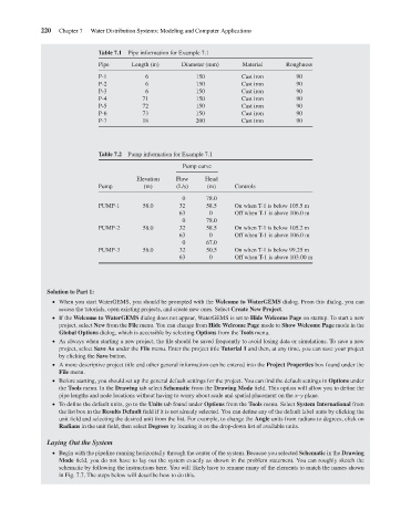
Table 7.1
Material
Pipe
Diameter (mm)
Length (m)
150
6
P-1
90
150
6
P-2
Cast iron
90
6
Cast iron
P-3
90
150
P-4
150
90
Cast iron
71
150
P-5
90
72
Cast iron
P-6
73
90
Cast iron
150
90
18
200
P-7
Cast iron
Pump information for Example 7.1
Table 7.2 Pipe information for Example 7.1 Cast iron Roughness
Pump curve
Elevation Flow Head
Pump (m) (L/s) (m) Controls
0 78.0
PUMP-1 58.0 32 58.5 On when T-1 is below 105.5 m
63 0 Off when T-1 is above 106.0 m
0 78.0
PUMP-2 58.0 32 58.5 On when T-1 is below 105.2 m
63 0 Off when T-1 is above 106.0 m
0 67.0
PUMP-3 58.0 32 50.5 On when T-1 is below 99.25 m
63 0 Off when T-1 is above 103.00 m
Solution to Part 1:
When you start WaterGEMS, you should be prompted with the Welcome to WaterGEMS dialog. From this dialog, you can
access the tutorials, open existing projects, and create new ones. Select Create New Project.
If the Welcome to WaterGEMS dialog does not appear, WaterGEMS is set to Hide Welcome Page on startup. To start a new
project, select New from the File menu. You can change from Hide Welcome Page mode to Show Welcome Page mode in the
Global Options dialog, which is accessible by selecting Options from the Tools menu.
As always when starting a new project, the file should be saved frequently to avoid losing data or simulations. To save a new
project, select Save As under the File menu. Enter the project title Tutorial 1 and then, at any time, you can save your project
by clicking the Save button.
A more descriptive project title and other general information can be entered into the Project Properties box found under the
File menu.
Before starting, you should set up the general default settings for the project. You can find the default settings in Options under
the Tools menu. In the Drawing tab select Schematic from the Drawing Mode field. This option will allow you to define the
pipe lengths and node locations without having to worry about scale and spatial placement on the x–y plane.
To define the default units, go to the Units tab found under Options from the Tools menu. Select System International from
the list box in the Results Default field if it is not already selected. You can define any of the default label units by clicking the
unit field and selecting the desired unit from the list. For example, to change the Angle units from radians to degrees, click on
Radians in the unit field, then select Degrees by locating it on the drop-down list of available units.
Laying Out the System
Begin with the pipeline running horizontally through the center of the system. Because you selected Schematic in the Drawing
Mode field, you do not have to lay out the system exactly as shown in the problem statement. You can roughly sketch the
schematic by following the instructions here. You will likely have to rename many of the elements to match the names shown
in Fig. 7.7. The steps below will describe how to do this.