
Page 241 - Water Engineering Hydraulics, Distribution and Treatment
P. 241
219
7.7 Automated Optimization
when grouping pipes and junctions because this could greatly
new pipe or rehabilitation of old pipe will be based on the
affect the model’s calibration accuracy.
following input hydraulic criteria:
Minimum and maximum allowable pressures
7.7.2 System Design
Minimum and maximum allowable pipe flow velocity
The goal of water distribution system design is to maximize
Additional demand requirements
the benefits of the system while minimizing the cost. The
optimal solution is a design that meets all the needs of the
Pipe, pump, tank, valve, and so on, status change
system at minimal cost. Some planning is needed to account
requirements
for additional future needs of the system including potential
Critical to creating an accurately designed system is time
growth of the system in terms of demand and its location.
The modeler must work with the system owner and planning or maximum benefit. In either case, the best solution for
and peak demand requirements. The peak demand and fire
groups to account for both the current and future needs. flow conditions are used to size pipes since the pipe network
Another module in WaterGEMS, called Darwin must work for all conditions. Using average demand values
Designer, assists engineers with the planning and design of to size pipe without accurately accounting for peaking factors
water distribution networks. Darwin Designer can be used can create networks that are either undersized and will not
to size new pipe and/or rehabilitate old pipes to minimize deliver the required water needs or oversized and much more
cost, maximize benefit, or create a scenario for trading off expensive than need be. The daily and seasonal variations
costs and benefits. The least cost optimization is used to can also greatly affect the final design. Demand variations
determine the pipe material and size needed to satisfy the need to be synchronized in the model to accurately reflect
design requirements. The maximum benefit optimization is what could happen in the real system.
used to determine the most beneficial solution based on a The following examples give step-by-step instructions
known budget. Darwin Designer will generate a number of on how to solve problems and design water systems using
solutions that meet the design requirements at minimal cost WaterGEMS.
EXAMPLE 7.1 THREE PUMPS IN PARALLEL
Problem Statement
A pump station is designed to supply water to a small linen factory. The factory, at an elevation of 58.0 m, draws from a circular,
constant-area tank (T-1) at a base elevation of 90.0 m with a minimum water elevation of 99.0 m, an initial water elevation of 105.5 m,
a maximum water elevation of 106.0 m, and a diameter of 10.0 m.
Three main parallel pumps draw water from a source with a water surface elevation of 58.0 m. Two pumps are set aside for
everyday usage, and the third is set aside for emergencies. Each pump has a set of controls that ensure it will run only when the water
level in the tank reaches a certain level. Use the Hazen–Williams equation to determine friction losses in the system. The network
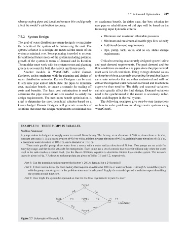
layout is given in Fig. 7.7; the pipe and pump data are given in Tables 7.1 and 7.2, respectively.
Part 1: Can the pumping station support the factory’s 20 L/s demand for a 24-h period?
Part 2: If there were a fire at the linen factory that required an additional 108 L/s of water for hours 0 through 6, would the system
with the pump controls given in the problem statement be adequate? Supply the extended-period simulation report describing
the system at each time step.
Part 3: How might the system be operated so that the fire flow requirement in part 2 is met?
Pump-3
P-2 P-6
Pond P-1 Pump-2 P-5 T-1 P-7
Linen factory
P-4
P-3
Pump-1
Figure 7.7 Schematic of Example 7.1.