
Page 34 - Water Engineering Hydraulics, Distribution and Treatment
P. 34
12
Introduction to Water Systems
Chapter 1
4. Slow sand filters pass water at rates of about 3 MGD/
acre (28 MLD/ha) in surface water filtration, stepping
up to about 10 MGD/acre (94 MLD/ha) in ground-
water treatment for iron and manganese removal or
when they are preceded by roughing filters.
5. Rapid filters operate at rates of 125 MGD/acre or
2
2 gpm/ft (1170 MLD/ha or 81 L/min/m ), but rates
run higher in modern works that include flocculating
chambers.
6. Coke tricklers for aeration are rated at about 75 MGD/
2
acre or 1.2 gpm/ft (700 MLD/ ha or 50 L/min/m ).
1.8 TRANSMISSION WORKS 2 2
Supply conduits, or aqueducts, transport water from the
source of supply to the community and so form the con-
necting link between collection works and distribution sys-
tems. Source location determines whether conduits are short
or long and whether transport is by gravity or pumping.
Depending on topography and available materials, conduits
are designed for open-channel or pressure flow. They may
follow the hydraulic grade line as canals dug through the
ground, flumes elevated above the ground, grade aqueducts
laid in balanced cut and cover at the ground surface, and
grade tunnels penetrating hills; or they may depart from
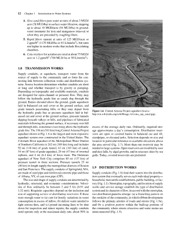
Figure 1.6 Central Arizona Project aqueduct (Source:
the hydraulic grade line as pressure aqueducts laid in bal-
http://en.wikipedia.org/wiki/Image:Arizona_cap_canal.jpg).
anced cut and cover at the ground surface, pressure tunnels
dipping beneath valleys or hills, and pipelines of fabricated
materials following the ground surface, if necessary over hill
and through dale, sometimes even rising above the hydraulic excess of the average daily rate. Ordinarily, required stor-
grade line. The 336 mi (541 km) long Central Arizona Project age approximates a day’s consumption. Distribution reser-
aqueduct shown in Fig. 1.6 is the largest and most expensive voirs are open or covered basins in balanced cut and fill,
aqueduct system ever constructed in the United States. The standpipes, or elevated tanks. Selection depends on size and
Colorado River aqueduct of the Metropolitan Water District location in particular reference to available elevations above
of Southern California is 242 mi (389 km) long and includes the area served (Fig. 1.7). More than one reservoir may be
92 mi (148 km) of grade tunnel, 63 mi (101 km) of canal, needed in large systems. Open reservoirs are troubled by soot
54 mi (87 km) of grade aqueduct, 29 mi (47 km) of inverted and dust falls, by algal growths, and in seacoast cities by sea
siphons, and 4 mi (6.4 km) of force main. The Delaware gulls. Today, covered reservoirs are preferred.
aqueduct of New York City comprises 85 mi (137 km) of
pressure tunnel in three sections. Pressure tunnels 25 mi
(40 km) in length supply the metropolitan districts of Boston
1.9 DISTRIBUTION WORKS
and San Francisco. The supply conduits of Springfield, MA,
are made of steel pipe and reinforced concrete pipe and those Supply conduits (Fig. 1.8) feed their waters into the distribu-
of Albany, NY, of cast-iron pipe (CIP). tion system that eventually serves each individual property—
The size and shape of supply conduits are determined by household, mercantile establishment, public building, or fac-
hydraulic, structural, and economic considerations. Veloci- tory (Fig. 1.1). Street plan, topography, and location of supply
ties of flow ordinarily lie between 3 and 5 ft/s (0.91 and works and service storage establish the type of distribution
1.52 m/s). Requisite capacities depend on the inclusion and system and its character of flow. In accord with the street plan,
size of supporting service or distributing reservoirs. If these two distribution patterns emerge: (a) a branching pattern on
store enough water to (a) care for hourly variations in water the outskirts of the community, in which ribbon development
consumption in excess of inflow, (b) deliver water needed to follows the primary arteries of roads and streets (Fig. 1.9a),
fight serious fires, and (c) permit incoming lines to be shut and (b) a gridiron pattern within the built-up portions of
down for inspection and minor repairs, the supply conduits the community where streets crisscross and water mains are
need operate only at the maximum daily rate, about 50% in interconnected (Fig. 1.9).