
Page 40 - Water Engineering Hydraulics, Distribution and Treatment
P. 40
18
Chapter 1
Introduction to Water Systems
Drop pipe
Pump
1˝ above top of concrete
Screen
6´
5˝
Detail at base of pump
6˝
Gravel
Natural ground surface
8˝ fill clay
Pipe drain Casing to extend at least Closed top Force
Soil
Cement grout
Waste trough may be
used instead of pipe
drain if desired
Fissured or
unsound rock
Sanitary Wrought-steel
base Bedrock drive-shoe
Watertight
joint
8˝ fill clay
Cylinder
Water-bearing
Alternate method of formation
setting pump
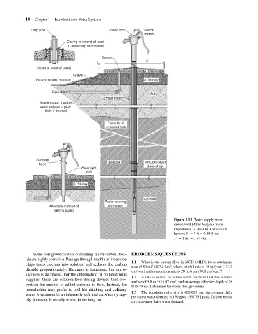
Figure 1.13 Water supply from
driven well (After Virginia State
Department of Health). Conversion
′
factors: 1 = 1ft = 0.3048 m;
′′
1 = 1in. = 2.54 cm.
Some soft groundwaters containing much carbon diox- PROBLEMS/QUESTIONS
ide are highly corrosive. Passage through marble or limestone
1.1 What is the stream flow in MGD (MLD) for a catchment
chips takes calcium into solution and reduces the carbon
2
2
area of 80 mi (207.2 km ) where rainfall rate is 45 in./year (114.3
dioxide proportionately. Hardness is increased, but corro-
cm/year) and evaporation rate is 20 in./year (50.8 cm/year)?
siveness is decreased. For the chlorination of polluted rural
1.2 A city is served by a raw water reservoir that has a water
supplies, there are solution-feed dosing devices that pro-
2
2
surface of 5.8 mi (15.02 km ) and an average effective depth of 18
portion the amount of added chlorine to flow. Instead, the
ft (5.49 m). Determine the water storage volume.
householder may prefer to boil his drinking and culinary
1.3 The population of a city is 400,000, and the average daily
water. Investment in an inherently safe and satisfactory sup-
per capita water demand is 150 gpcd (567.75 Lpcd). Determine the
ply, however, is usually wisest in the long run.
city’s average daily water demand.