
Page 302 - Water Loss Control
P. 302
Contr olling Real Losses in the Field—Pr oactive Leak Detection 271
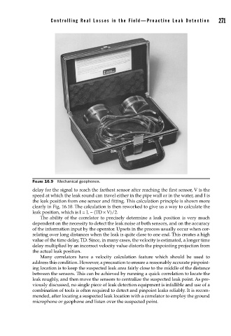
FIGURE 16.9 Mechanical geophones.
delay for the signal to reach the farthest sensor after reaching the first sensor, V is the
speed at which the leak sound can travel either in the pipe wall or in the water, and I is
the leak position from one sensor and fitting. This calculation principle is shown more
clearly in Fig. 16.10. The calculation is then reworked to give us a way to calculate the
leak position, which is I = L − (TD × V)/2.
The ability of the correlator to precisely determine a leak position is very much
dependent on the necessity to detect the leak noise at both sensors, and on the accuracy
of the information input by the operator. Upsets in the process usually occur when cor-
relating over long distances when the leak is quite close to one end. This creates a high
value of the time delay, TD. Since, in many cases, the velocity is estimated, a longer time
delay multiplied by an incorrect velocity value distorts the pinpointing projection from
the actual leak position.
Many correlators have a velocity calculation feature which should be used to
address this condition. However, a precaution to ensure a reasonably accurate pinpoint-
ing location is to keep the suspected leak area fairly close to the middle of the distance
between the sensors. This can be achieved by running a quick correlation to locate the
leak roughly, and then move the sensors to centralize the suspected leak point. As pre-
viously discussed, no single piece of leak detection equipment is infallible and use of a
combination of tools is often required to detect and pinpoint leaks reliably. It is recom-
mended, after locating a suspected leak location with a correlator to employ the ground
microphone or geophone and listen over the suspected point.