
Page 316 - Water Loss Control
P. 316
Contr olling Real Losses in the Field—Pr oactive Leak Detection 285
• The configuration of the distribution network pump system and location of
pumping stations need to be carefully assessed and included in the design
stage.
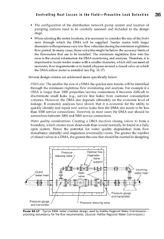
• When selecting the meter locations, it is necessary to consider the size of the feeder
main through which the DMA will be supplied. Feeder mains with larger
diameters will experience very low flow velocities during the minimum nighttime
flow period. In many cases, those velocities might be below the accuracy limits of
the flowmeters that are to be installed. The minimum nighttime flow into the
zone is the crucial information for DMA monitoring and analysis. Therefore, it is
important to locate feeder mains with a smaller diameter, which still can meet all
necessary flow requirements or to install a bypass around a closed valve on which
the DMA inflow meter is installed (see Fig. 16.17).
Several design criteria are addressed more specifically below
DMA size: The smaller the size of a DMA the quicker new breaks will be identified
through the minimum nighttime flow monitoring and analysis. For example if a
DMA is larger than 1000 properties/service connections it becomes difficult to
discriminate small leaks (e.g., service line leaks) from customer consumption
volumes. However, the DMA size depends ultimately on the economic level of
leakage. If economic analyses have shown that it is economic for the utility to
quickly identify and repair new service leaks then the DMA size needs to be less
than 1000 service connections. However, in most cases the DMA size should be
somewhere between 3000 and 5000 service connections.
Water quality considerations: Creating a DMA involves closing valves to form a
boundary, which creates more dead-ends than would normally be found in a fully
open system. Hence the potential for water quality degradation from flow
disturbance (initially) and stagnation (eventually) exists. The greater the number
of closed valves in a DMA, the greater the care that should be exerted in designing
Pressure Optimal flow
reducing valve magmeter
Valve
support
M Incoming
Outlet Gate water main
water main valve
Pressure gauge
and transmitter
Pressure gauge Pressure reducing valve
and transmitter
FIGURE 16.17 Typical DMA meter chamber design used by Halifax Regional Water Commission—
providing redundancy for fi re fl ow requirements. (Source: Halifax Regional Water Commission.)