
Page 313 - Water Loss Control
P. 313
282 Cha pte r S i x tee n
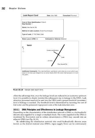
Leak Report Card Date June 1995 Consultant Thornton
Area or Zone Identification: Zone 3
Map Number: 1
Street: Rex Harrell Rd
Method of Leak Location: Zone Flow Analysis
Type of Leak: 2’’ PVC Main Split
Water Loss in GPM: 44 Estimated or Metered: Metered
Sketch
N
Unaka subdivision
Leak
2” PVC
Rex Harrell Rd
Additional Comments: This leak had been running for some time as a rock which was
close to the leak was shaped like an arrow head where the water had sprayed on it over
the years.
FIGURE 16.15 Sample leak report form.
offers the advantage that, once the leakage levels are reduced to an economic optimum
level, it is possible to closely monitor the subsequent rise in leakage in the DMA. Leak
detection personnel need not be sent into the DMA until a preset threshold (economic)
level of leakage is reached. The threshold level is determined by factoring the cost of
lost water and the personnel/equipment costs of the leak detection crew.
16.6.1 DMA Principles and Effectiveness in Leakage Management
Depending on the characteristics of the distribution network a DMA is a hydraulically
discrete area supplied by a single or multiple feeds. The water supplied to the DMA is
monitored by flowmeters and in certain circumstances a DMA may cascade into an
adjacent DMA (see Fig. 16.16).
By subdividing the distribution network into small hydraulically discrete areas
known as the district metered area (DMA), input supply flows can be continuously