Page 141 - Water and wastewater engineering
P. 141

3-38   WATER AND WASTEWATER ENGINEERING

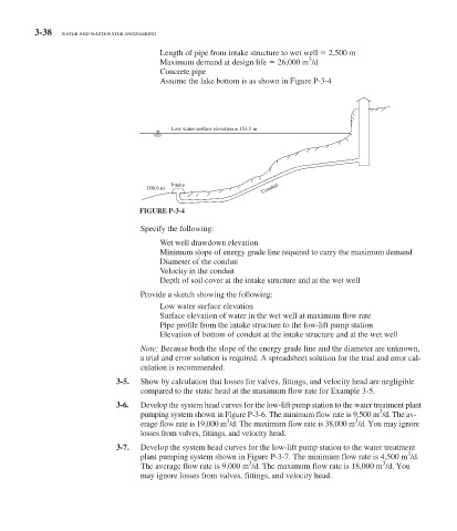
                                              Length of pipe from intake structure to wet well     2,500 m
                                                                                3
                                            Maximum demand at design life     26,000 m  /d
                                            Concrete pipe
                                            Assume the lake bottom is as shown in  Figure P-3-4


                                             Low water surface elevation = 153.5 m


                                             Intake
                                       106.6 m                      Conduit

                                     FIGURE P-3-4
                                          Specify the following:
                                             Wet well drawdown elevation
                                            Minimum slope of energy grade line required to carry the maximum demand
                                            Diameter of the conduit
                                            Velocity in the conduit
                                            Depth of soil cover at the intake structure and at the wet well

                                     Provide a sketch showing the following:
                                             Low water surface elevation
                                            Surface elevation of water in the wet well at maximum fl ow rate
                                            Pipe profi le from the intake structure to the low-lift pump station
                                            Elevation of bottom of conduit at the intake structure and at the wet well
                                     Note:  Because both the slope of the energy grade line and the diameter are unknown,
                                     a trial and error solution is required. A spreadsheet solution for the trial and error cal-
                                     culation is recommended.

                                  3-5.    Show by calculation that losses for valves, fittings, and velocity head are negligible
                                     compared to the static head at the maximum flow rate for Example 3-5.
                                  3-6.    Develop the system head curves for the low-lift pump station to the water treatment plant
                                                                                                  3
                                     pumping system shown in   Figure P-3-6 . The minimum flow rate is 9,500 m  /d. The av-
                                                           3
                                                                                            3
                                     erage flow rate is 19,000 m  /d. The maximum flow rate is 38,000 m  /d. You may ignore
                                     losses from valves, fittings, and velocity head.
                                       3-7.    Develop the system head curves for the low-lift pump station to the water treatment
                                                                                                         3
                                     plant pumping system shown in  Figure P-3-7 . The minimum flow rate is 4,500 m  /d.
                                                                                                   3
                                                                 3
                                     The average flow rate is 9,000 m  /d. The maximum flow rate is 18,000 m  /d. You
                                     may ignore losses from valves, fittings, and velocity head.
   136   137   138   139   140   141   142   143   144   145   146