
Page 150 - Water and wastewater engineering
P. 150
WELLS 4-5
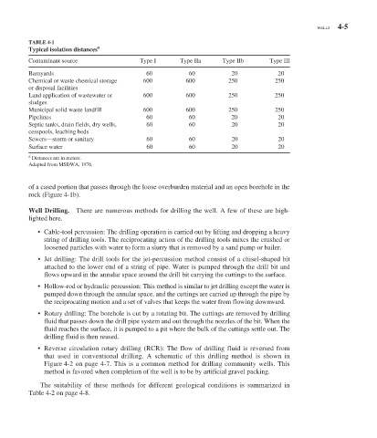
TABLE 4-1
a
Typical isolation distances
Contaminant source Type I Type IIa Type IIb Type III
Barnyards 60 60 20 20
Chemical or waste chemical storage 600 600 250 250
or disposal facilities
Land application of wastewater or 600 600 250 250
sludges
Municipal solid waste landfill 600 600 250 250
Pipelines 60 60 20 20
Septic tanks, drain fields, dry wells, 60 60 20 20
cesspools, leaching beds
Sewers—storm or sanitary 60 60 20 20
Surface water 60 60 20 20
a
Distances are in meters.
Adapted from MSDWA, 1976.
of a cased portion that passes through the loose overburden material and an open borehole in the
rock ( Figure 4-1 b).
Well Drilling. There are numerous methods for drilling the well. A few of these are high-
lighted here.
• Cable-tool percussion: The drilling operation is carried out by lifting and dropping a heavy
string of drilling tools. The reciprocating action of the drilling tools mixes the crushed or
loosened particles with water to form a slurry that is removed by a sand pump or bailer.
• Jet drilling: The drill tools for the jet-percussion method consist of a chisel-shaped bit
attached to the lower end of a string of pipe. Water is pumped through the drill bit and
flows upward in the annular space around the drill bit carrying the cuttings to the surface.
• Hollow-rod or hydraulic percussion: This method is similar to jet drilling except the water is
pumped down through the annular space, and the cuttings are carried up through the pipe by
the reciprocating motion and a set of valves that keeps the water from flowing downward.
• Rotary drilling: The borehole is cut by a rotating bit. The cuttings are removed by drilling
fluid that passes down the drill pipe system and out through the nozzles of the bit. When the
fluid reaches the surface, it is pumped to a pit where the bulk of the cuttings settle out. The
drilling fluid is then reused.
• Reverse circulation rotary drilling (RCR): The flow of drilling fluid is reversed from
that used in conventional drilling. A schematic of this drilling method is shown in
Figure 4-2 on page 4-7. This is a common method for drilling community wells. This
method is favored when completion of the well is to be by artificial gravel packing.
The suitability of these methods for different geological conditions is summarized in
Table 4-2 on page 4-8.