
Page 154 - Water and wastewater engineering
P. 154
WELLS 4-9
Pump
Mixer
Grout overflow Grout
Top soil
Grout pipe
Drilled hole
diameter at
Steel casing
least 5 cm
larger than
well casing
Well casing Non-caving
Rubber seat
formation
(clay)
Plastic ball valve
Casing filled
Plastic cage
with water or
mud fluid
Concrete
Grout
Fractured
bedrock
Pipe off
the bottom
(a) (b)
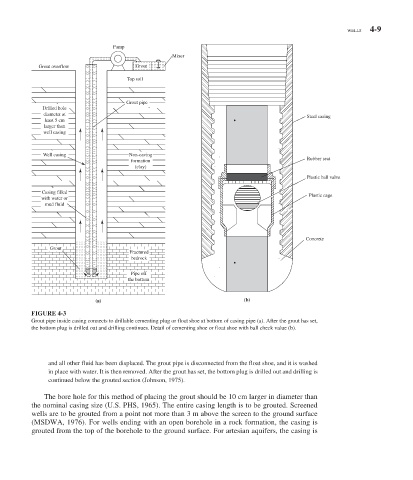
FIGURE 4-3
Grout pipe inside casing connects to drillable cementing plug or float shoe at bottom of casing pipe (a). After the grout has set,
the bottom plug is drilled out and drilling continues. Detail of cementing shoe or float shoe with ball check value (b).
and all other fluid has been displaced. The grout pipe is disconnected from the float shoe, and it is washed
in place with water. It is then removed. After the grout has set, the bottom plug is drilled out and drilling is
continued below the grouted section (Johnson, 1975).
The bore hole for this method of placing the grout should be 10 cm larger in diameter than
the nominal casing size (U.S. PHS, 1965). The entire casing length is to be grouted. Screened
wells are to be grouted from a point not more than 3 m above the screen to the ground surface
(MSDWA, 1976). For wells ending with an open borehole in a rock formation, the casing is
grouted from the top of the borehole to the ground surface. For artesian aquifers, the casing is