
Page 156 - Water and wastewater engineering
P. 156
WELLS 4-11
Drill Casing
Minimum of Water level in bore hole Neat cement grout
4 m of water at start
Temporary surface casing
of drilling below
temporary casing Casing
Approx 8 m
welded
Screen
to
screen
Gravel pack
Reverse circulation
rotary bit
Bore hole
(a) (b)
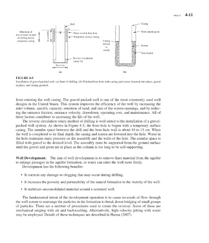
FIGURE 4-5
Installation of gravel-packed well. ( a ) Start of drilling. ( b ) Finished bore hole with casing and screen lowered into place, gravel
in place, and casing grouted.
from entering the well casing. The gravel-packed well is one of the most commonly used well
designs in the United States. This system improves the efficiency of the well by increasing the
inlet volume, specific capacity, retention of sand, and size of the screen openings, and by reduc-
ing the entrance friction, entrance velocity, drawdown, operating cost, and maintenance. All of
these factors contribute to increasing the life of the well.
The reverse circulation rotary method of drilling is well suited to the installation of a gravel-
packed well system. As shown in Figure 4-5 , the bore-hole is begun with a temporary surface
casing. The annular space between the drill and the bore-hole wall is about 10 to 15 cm. When
the well is completed to its final depth, the casing and screen are lowered into the hole. Water in
the hole maintains static pressure on the assembly and the walls of the hole. The annular space is
filled with gravel to the desired level. The assembly must be supported from the ground surface
until the gravel and grout are in place as the column is too long to be self-supporting.
Well Development. The aim of well development is to remove finer material from the aquifer
to enlarge passages in the aquifer formation, so water can enter the well more freely.
Development has the following benefits:
• It corrects any damage or clogging that may occur during drilling.
• It increases the porosity and permeability of the natural formation in the vicinity of the well.
• It stabilizes unconsolidated material around a screened well.
The fundamental intent of the development operation is to cause reversals of flow through
the well screen to rearrange the particles in the formation to break down bridging of small groups
of particles. There are a number of procedures used to create the reversal. Some of these are
mechanical surging with air and backwashing. Alternatively, high-velocity jetting with water
may be employed. Details of these techniques are described in Hanna (2007).