
Page 153 - Water and wastewater engineering
P. 153
4-8 WATER AND WASTEWATER ENGINEERING
TABLE 4-2
a
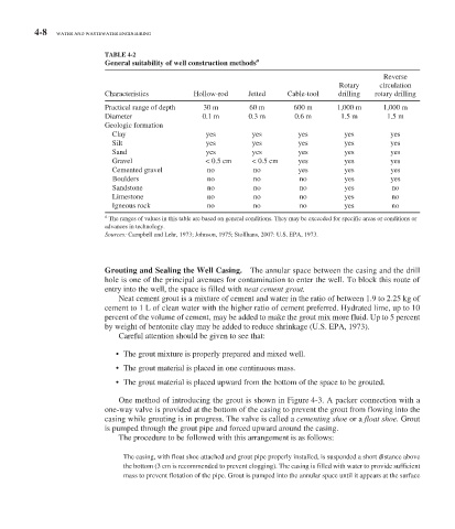
General suitability of well construction methods
Reverse
Rotary circulation
Characteristics Hollow-rod Jetted Cable-tool drilling rotary drilling
Practical range of depth 30 m 60 m 600 m 1,000 m 1,000 m
Diameter 0.1 m 0.3 m 0.6 m 1.5 m 1.5 m
Geologic formation
Clay yes yes yes yes yes
Silt yes yes yes yes yes
Sand yes yes yes yes yes
Gravel < 0.5 cm < 0.5 cm yes yes yes
Cemented gravel no no yes yes yes
Boulders no no no yes yes
Sandstone no no no yes no
Limestone no no no yes no
Igneous rock no no no yes no
a
The ranges of values in this table are based on general conditions. They may be exceeded for specific areas or conditions or
advances in technology.
Sources: Campbell and Lehr, 1973; Johnson, 1975; Stollhans, 2007: U.S. EPA, 1973.
Grouting and Sealing the Well Casing. The annular space between the casing and the drill
hole is one of the principal avenues for contamination to enter the well. To block this route of
entry into the well, the space is filled with neat cement grout.
Neat cement grout is a mixture of cement and water in the ratio of between 1.9 to 2.25 kg of
cement to 1 L of clean water with the higher ratio of cement preferred. Hydrated lime, up to 10
percent of the volume of cement, may be added to make the grout mix more fluid. Up to 5 percent
by weight of bentonite clay may be added to reduce shrinkage (U.S. EPA, 1973).
Careful attention should be given to see that:
• The grout mixture is properly prepared and mixed well.
• The grout material is placed in one continuous mass.
• The grout material is placed upward from the bottom of the space to be grouted.
One method of introducing the grout is shown in Figure 4-3 . A packer connection with a
one-way valve is provided at the bottom of the casing to prevent the grout from flowing into the
casing while grouting is in progress. The valve is called a cementing shoe or a float shoe. Grout
is pumped through the grout pipe and forced upward around the casing.
The procedure to be followed with this arrangement is as follows:
The casing, with float shoe attached and grout pipe properly installed, is suspended a short distance above
the bottom (3 cm is recommended to prevent clogging). The casing is filled with water to provide sufficient
mass to prevent flotation of the pipe. Grout is pumped into the annular space until it appears at the surface