
Page 160 - Water and wastewater engineering
P. 160
WELLS 4-15
Hatch
or
removable
Heat lamp
roof/walls
Shingles and
sheathing
Insulation
Ventilation Rafters
Pump motor
Sanitary
well seal Control Studs
box Sheathing
Reinforced
0.6 m Siding
concrete
0.1 m
Protective Surface soil
casing
Frost line
To water plant Clay 6 m
Grout seal
Well casing
Discharge pipe
Pump
Casing shoe
Well screen
Water-bearing sand or gravel
Closed ball bottom
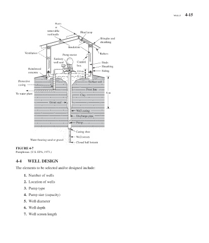
FIGURE 4-7
Pumphouse. (U.S. EPA, 1973.)
4-4 WELL DESIGN
The elements to be selected and/or designed include:
1. Number of wells
2. Location of wells
3. Pump type
4. Pump size (capacity)
5. Well diameter
6. Well depth
7. Well screen length