
Page 267 - Water and wastewater engineering
P. 267
6-44 WATER AND WASTEWATER ENGINEERING
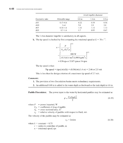
Axial impeller diameter
Geometric ratio Allowable range 0.8 m 1.4 m 2.0 m
D/T 0.17 – 0.4 0.22 0.39 0.56
H/D 2– 4 5.0 2.9 2.0
H/T 0.34 –1.6 1.12 1.12 1.12
B/D 0.7–1.6 1.7 0.95 0.67
The 1.4 m diameter impeller is satisfactory in all aspects.
1
k. The tip speed is checked by first computing the rotational speed at G 70 s .
/
⎡ ⎤ 13
n ⎢ P ⎥
⎢ ND ) ⎥
5
(
⎣ p i ⎦
/
⎡ 300 W ⎤ 13
⎢ ⎥
⎣ ⎢ ( . ) . 5 kg/m 3 ) ⎥ ⎦
(
031 1 4 m))(1 000,
056 rpsor 3387 rrpmor 34 rpm
.
.
The tip speed is then
.
.
.
.
Tip speed ( ) ) (0 56 )()(1 4 m 2 46 or 2 5 m/s
6
)
rps ()(D i
This is less than the design criterion of a maximum tip speed of 2.7 m/s.
Comments:
1. The provision of two flocculation basins meets redundancy requirements.
2. An additional 0.60 m is added to the water depth as freeboard so the tank depth is 4.6 m.
Paddle Flocculator. The power input to the water by horizontal paddles may be estimated as
p
CA v p 3
D
P (6-19)
2
where P power imparted, W
C D coefficient of drag of paddle
2
A p cross-sectional area, m
v p relative velocity of paddles with respect to fluid, m/s
The velocity of the paddles may be estimated as
v p 2 krn (6-20)
where k constant 0.75
r radius to centerline of paddle, m
n rotational speed, rps