
Page 264 - Water and wastewater engineering
P. 264
COAGULATION AND FLOCCULATION 6-41
n. Execute solve to find the number of cells is 58.44863. Because this is not an integer, it is
NOT the final answer. Acceptable answers are 59 or 60 orifices. The velocity and headloss
may be checked by typing the integer in cell [B9].
Comments:
1. This design calculation lends itself to a spreadsheet because the design is iterative in
selecting the appropriate number of orifices.
2. A scale drawing of the orifices on the cross section of the baffle will provide a visual
check on the reasonableness of the design.
Mixer Alternatives. Flocculation is normally accomplished with one of the following
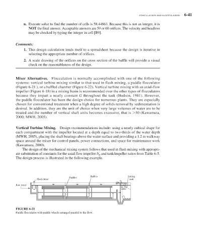
systems: vertical turbine mixing similar to that used in flash mixing, a paddle flocculator
( Figure 6-21 ), or a baffled chamber ( Figure 6-22 ). Vertical turbine mixing with an axial-flow
impeller ( Figure 6-18 ) in a mixing basin is recommended over the other types of flocculators
because they impart a nearly constant G throughout the tank (Hudson, 1981). However,
the paddle flocculator has been the design choice for numerous plants. They are especially
chosen for conventional treatment when a high degree of solids removal by sedimentation is
desired. In addition, they are the unit of choice when very large volumes of water are to be
treated and the number of vertical shaft units becomes excessive, that is 50 (Kawamura,
2000; MWH, 2005).
Vertical Turbine Mixing. Design recommendations include: using a nearly cubical shape for
each compartment with the impeller located at a depth equal to two-thirds of the water depth
(MWH, 2005), placing the shaft bearings above the water surface and providing a 1.2 m walkway
space around the mixer for control panels, power connections, and space for maintenance work
(Kawamura, 2000).
The design of the mechanical mixing system follows that used in flash mixing with appropri-
ate substitution of constants for the axial flow impeller N p and tank/impeller ratios from Table 6-5 .
The design process is illustrated in the following example.
Baffles Setting
Paddles
Flash mixer tank
Raw water
FIGURE 6-21
Paddle flocculator with paddle wheels arranged parallel to the flow.