
Page 261 - Water and wastewater engineering
P. 261
6-38 WATER AND WASTEWATER ENGINEERING
Paddle flocculator
Baffle wall
Baffle walls
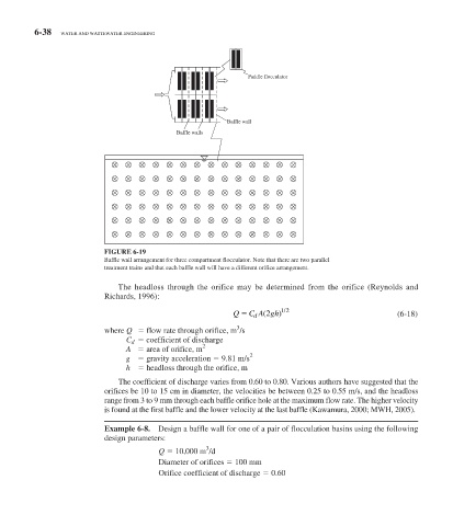
FIGURE 6-19
Baffle wall arrangement for three compartment flocculator. Note that there are two parallel
treatment trains and that each baffle wall will have a different orifice arrangement.
The headloss through the orifice may be determined from the orifice (Reynolds and
Richards, 1996):
/
Q C A gh) 12 (6-18)
(
2
d
3
where Q flow rate through orifice, m /s
C d coefficient of discharge
2
A area of orifice, m
2
g gravity acceleration 9.81 m/s
h headloss through the orifice, m
The coefficient of discharge varies from 0.60 to 0.80. Various authors have suggested that the
orifices be 10 to 15 cm in diameter, the velocities be between 0.25 to 0.55 m/s, and the headloss
range from 3 to 9 mm through each baffle orifice hole at the maximum flow rate. The higher velocity
is found at the first baffle and the lower velocity at the last baffle (Kawamura, 2000; MWH, 2005).
Example 6-8. Design a baffle wall for one of a pair of flocculation basins using the following
design parameters:
3
Q 10,000 m /d
Diameter of orifices 100 mm
Orifice coefficient of discharge 0.60