Page 259 - Water and wastewater engineering
P. 259

6-36   WATER AND WASTEWATER ENGINEERING

                                 d.  The required input water power can be calculated by using Equation 6-12. Using Table
                                                                                                      3
                                   A-1 in Appendix A and the temperature of the water, find         1.519     10    Pa · s.

                                                    12           3             3
                                                         .
                                                                      s
                                                                                    6
                                                                         .
                                           P  (600 s  ) (1 519  10  Pa 
 )(0 665 m  )   363 6.or  360 W
                                   Because the efficiency of transfer of motor power to water power is about 80%, the
                                   motor power should be
                                                                       360  W
                                                         Motor power           450  W
                                                                         08
                                                                          .
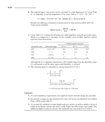
                                 e.  Using  Table 6-5 , evaluate the different size radial impellers using the geometric ratios.
                                   Below is a comparison of the ratios for the available sizes of radial impellers and the
                                   rapid mix basin dimensions.

                                                                           Radial impeller diameter
                                    Geometric ratio  Allowable range  0.3 m       0.4 m        0.5 m
                                    D/T               0.14 – 0.5       0.4          0.53        0.67
                                    H/D                 2 – 4          5.0          3.8         3.0
                                    H/T                0.28–2          2            2           2
                                    B/D                0.7–1.6         1.7          1.3         1.0

                                         Although the 0.4 m diameter impeller has a  D / T  slightly larger than the allowable range,
                                   it is satisfactory in all the other aspects and, therefore, is selected.
                                 f.  The rotational speed is calculated by solving  Equation 6-17  for  n:

                                                                    /
                                                         ⎡         ⎤ 13
                                                      n ⎢     P    ⎥
                                                                5
                                                         ⎢ ⎣ N D i )   ⎥ ⎦
                                                            p (
                                                                                    /
                                                         ⎡         450 W          ⎤ 13
                                                        ⎢                         ⎥
                                                         ⎣ ⎢ ( .  ) .  5 5  kg/m 3 )⎥ ⎦
                                                           57 04 m) 1 000( ,
                                                              (
                                                         1 976 rps or  118 5 rrpm or 120 rpm
                                                                       .
                                                          .
                              Comments:
                                  1.  To meet redundancy requirements, two rapid mix basins with this design are provided.
                                 2.  Because the average day and minimum flow rates will be less, the detention time at these
                                   flows will be longer than 5 s.
                                 3.  To account for variations in water height and wave action, as well as adding a factor of
                                   safety in the design volume, the tank is made deeper than the design water depth. This
                                   additional depth is called  freeboard.  The freeboard may vary from 0.45 to 0.60 m.
   254   255   256   257   258   259   260   261   262   263   264