
Page 256 - Water and wastewater engineering
P. 256
COAGULATION AND FLOCCULATION 6-33
i. Estimate Gt.
1
Gt (241 .9 s )(10.9 ) s 2 636 .7 or 2 600
,
,
Comments:
1. The detention time and Gt criteria were not met. At this point in the design calculation,
another trial would be attempted. The variables that can be explored are the diameter of
the pipe and the number of elements (by assuming a less stringent COV). Alternatively,
another manufacturer’s mixer may be suitable under the assumptions given.
2. When the final design is selected, two mixers of this size would be provided for
redundancy.
3. The failure of this design to meet the design criteria will be exacerbated when the flow
rate is at the average and minimum flow rates. For this reason alone, static mixers have
limited application in mixing coagulant.
4. Because this is an iterative problem, it is well suited to a spreadsheet solution.
Mechanical Mixing in Stirred Tanks. When the predominant coagulation mechanism is sweep
coagulation, extremely short mixing times are not as important, as in adsorption-destabilization.
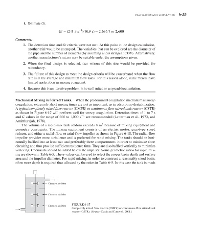
A typical completely mixed flow reactor (CMFR) or continuous-flow stirred tank reactor (CSTR)
as shown in Figure 6-17 will perform well for sweep coagulation. Detention times of 1 to 7 s
1
and G values in the range of 600 to 1,000 s are recommended (Letterman et al., 1973, and
Amirtharajah, 1978).
3
The volume of a rapid-mix tank seldom exceeds 8 m because of mixing equipment and
geometry constraints. The mixing equipment consists of an electric motor, gear-type speed
reducer, and either a radial-flow or axial-flow impeller as shown in Figure 6-18 . The radial-flow
impeller provides more turbulence and is preferred for rapid mixing. The tanks should be hori-
zontally baffled into at least two and preferably three compartments in order to minimize short
circuiting and thus provide sufficient residence time. They are also baffled vertically to minimize
vortexing. Chemicals should be added below the impeller. Some geometric ratios for rapid mix-
ing are shown in Table 6-5 . These values can be used to select the proper basin depth and surface
area and the impeller diameter. For rapid mixing, in order to construct a reasonably sized basin,
often more depth is required than allowed by the ratios in Table 6-5 . In this case the tank is made
Chemical addition
Chemical addition
FIGURE 6-17
Chemical addition
Completely mixed flow reactor (CMFR) or continuous-flow stirred tank
reactor (CSTR). (Source: Davis and Cornwell, 2008.)