
Page 370 - Water and wastewater engineering
P. 370
REVERSE OSMOSIS AND NANOFILTRATION 9-9
Pressure vessel Anti-telescoping Concentrate (brine)
support seal
Snap ring
Permeate
Membrane Membrane Membrane End cap
water element element element
Concentrate module module module Source water inlet
outlet
Brine seals O-ring
connector
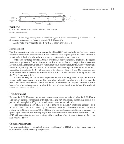
FIGURE 9-6
Cross section of pressure vessel with three spiral-wound RO elements.
( Source: U.S. AID, 1980.)
extracted. A two-stage arrangement is shown in Figure 9-7 a and schematically in Figure 9-7 b. A
three-stage arrangement is shown schematically in Figure 9-7 c.
A schematic of a typical RO or NF facility is shown in Figure 9-8 .
Pretreatment
The first pretreatment is to prevent scaling by silica (SiO 2 ) and sparingly soluble salts such as
calcium carbonate and calcium sulfate. Scale control consists of pH adjustment and/or addition of
an antiscalant. Typically, the antiscalants are proprietary polymeric compounds.
Unlike ion exchange columns, RO/NF systems are not backwashed. Therefore, the second
pretreatment process is filtration to remove particulate matter that will clog the feed channels or
accumulate on the membrane surface. For surface water sources granular filtration or membrane
filtration may be required. The minimum filtration requirement regardless of the water source is
a cartridge filter rated in the 1 to 25 m range with a typical rating of 5 m. The maximum feed
water turbidity recommended by manufacturers is 1 NTU with a preferred turbidity of less than
0.2 NTU (Bergman, 2005).
Disinfection may also be required to prevent biological fouling. Even though groundwater
is expected to have a very low microbial population, when the membrane is out of service, the
population on the membrane can quickly multiply. Chlorine solutions may be used for CA mem-
branes, but other techniques such as ultraviolet irradiation, or chlorination followed by dechlori-
nation are used for PA membranes.
Post-treatment
Because the RO/NF membranes do not remove gases, these are stripped after the RO/NF unit.
The primary gases of concern are hydrogen sulfide and carbon dioxide. The removal of H 2 S is to
prevent odor complaints. CO 2 is removed because it forms carbonic acid.
The permeate has a low pH as a result of removal of alkalinity (buffering capacity) from
the water and the addition of acid to prevent scaling. This water is corrosive to the distribution
system. In addition to stripping CO 2 , addition of a base and corrosion inhibitor is generally re-
quired. Split treatment and blending may aid in corrosion control. Maximum Contaminant Limits
(MCLs) for constituents such as arsenic must be considered if split treatment is part of the corro-
sion control strategy.
Concentrate Stream
The concentrate stream is under high pressure as it leaves the RO/NF unit. Energy recovery sys-
tems are often used in reducing the pressure.