
Page 371 - Water and wastewater engineering
P. 371
9-10 WATER AND WASTEWATER ENGINEERING
Stage 1: Stage 2:
24 Vessels 12 Vessels
144 Elements 72 Elements
Permeate
Feed Concentrate
Feed
Concentrate
Plan view End-perspective view
(a)
Permeate
(product)
Concentrate
(reject)
(brine)
(b)
Concentrate
Permeate
Permeate
Permeate
(c)
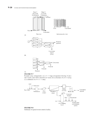
FIGURE 9-7
Example array arrangements: (a) a 4 2 stage arrangement showing 12 pres-
sure vessels, each with 6 elements per vessel; ( b ) a schematic of a 4 2 array;
( c ) a schematic of a 4 2 1 array.
Acid
Antiscalant
Energy
Raw water recovery Concentrate
Prefiltration Feed Membrane Break tank disposal
pumps arrays CO
2
Corrosion
inhibitor
Base Disinfectant
Air
Treated water
CO stripping
2 to distribution
tower
system
FIGURE 9-8
Schematic of typical reverse osmosis facility.