
Page 416 - Water and wastewater engineering
P. 416
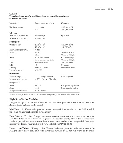
SEDIMENTATION 10-33

            TABLE 10-5
            Typical design criteria for small to medium horizontal-flow rectangular
          sedimentation basins

          Parameter               Typical range of values  Comment
                                                                    3
          Number of tanks         1   1 spare              < 10,000 m /d
                                                                    3
                                   2                        20,000 m /d
          Inlet zone
          Distance to diffuser wall  4% of length          up to 2 m
          Diffuser hole diameter  0.10–0.20 m
          Settling zone
                                                                    3
                                      3
          Overflow rate           20 m /d · m 2            < 10,000 m /d
                                      3
                                                                   3
                                  40 m /d · m 2            >10,000 m /d
          Side water depth (SWD)  3–5 m
          Length                  30 m                     Wind constraint
                                  60 m                     Chain-and-flight
          Width                   0.3 m increments         Chain-and-flight
                                  6 m maximum per train    Chain-and-flight
          L:W                     minimum of 4:1            6:1 preferred
          L:D                     15:1                     Minimum
          Velocity                0.005–0.018 m/s          Horizontal, mean
          Reynolds number         < 20,000

          Outlet zone
          Launder length          1/3–1/2 length of basin  Evenly spaced
                                         3
          Launder weir loading      250 m /d · m of launder
          Sludge zone
          Depth                   0.6–1 m                  Equipment dependent
          Slope                   1:600                    Mechanical cleaning
          Sludge collector speed  0.3–0.9 m/min
             Sources:  AWWA, 1990; GLUMRB, 2003; Kawamura, 2000; MWH, 2005; Walker, 1978; Willis, 2005.
             High-Rate Settler Modules
           The guidance provided for the number of tanks for rectangular horizontal flow sedimentation
          also applies to high-rate settler modules.

            Inlet Zone.  A diffuser is designed and placed in the tank inlet zone in the same fashion as it is
          for a plain rectangular horizontal flow clarifier.

            Flow Pattern.  The three flow patterns, countercurrent, cocurrent, and crosscurrent, in theory,

          have little difference in performance. In practice the countercurrent pattern is the one most com-
          monly employed because cocurrent designs often have trouble with resuspended sludge and
          crosscurrent designs have trouble with flow distribution (MWH, 2005).

            Plates versus Tubes.  Although little difference has been reported for various tube shapes, the
          hexagon and v-shapes may have some advantage because the sludge can collect in the notch.