
Page 411 - Water and wastewater engineering
P. 411
10-28 WATER AND WASTEWATER ENGINEERING
orifices may be used on the launders. These have been used to avoid breakup of fragile floc when
conventional rapid sand filters are used. For high-rate filter designs, there is less concern about
breaking the floc because high-rate filters require a small strong floc, and filter aids are added
prior to filtration to improve particle attachment in the filter.
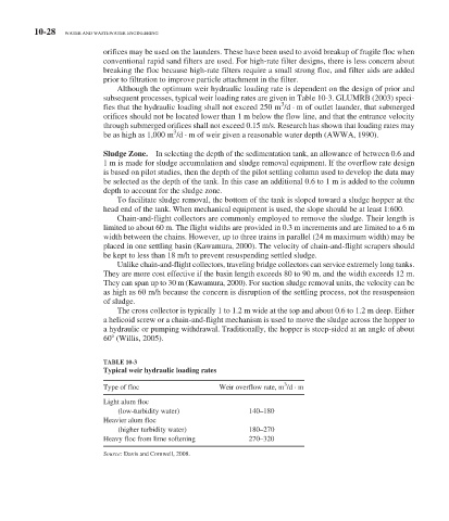
Although the optimum weir hydraulic loading rate is dependent on the design of prior and
subsequent processes, typical weir loading rates are given in Table 10-3 . GLUMRB (2003) speci-
3
fies that the hydraulic loading shall not exceed 250 m /d · m of outlet launder, that submerged
orifices should not be located lower than 1 m below the flow line, and that the entrance velocity
through submerged orifices shall not exceed 0.15 m/s. Research has shown that loading rates may
3
be as high as 1,000 m /d · m of weir given a reasonable water depth (AWWA, 1990).
Sludge Zone. In selecting the depth of the sedimentation tank, an allowance of between 0.6 and
1 m is made for sludge accumulation and sludge removal equipment. If the overflow rate design
is based on pilot studies, then the depth of the pilot settling column used to develop the data may
be selected as the depth of the tank. In this case an additional 0.6 to 1 m is added to the column
depth to account for the sludge zone.
To facilitate sludge removal, the bottom of the tank is sloped toward a sludge hopper at the
head end of the tank. When mechanical equipment is used, the slope should be at least 1:600.
Chain-and-flight collectors are commonly employed to remove the sludge. Their length is
limited to about 60 m. The flight widths are provided in 0.3 m increments and are limited to a 6 m
width between the chains. However, up to three trains in parallel (24 m maximum width) may be
placed in one settling basin (Kawamura, 2000). The velocity of chain-and-flight scrapers should
be kept to less than 18 m/h to prevent resuspending settled sludge.
Unlike chain-and-flight collectors, traveling bridge collectors can service extremely long tanks.
They are more cost effective if the basin length exceeds 80 to 90 m, and the width exceeds 12 m.
They can span up to 30 m (Kawamura, 2000). For suction sludge removal units, the velocity can be
as high as 60 m/h because the concern is disruption of the settling process, not the resuspension
of sludge.
The cross collector is typically 1 to 1.2 m wide at the top and about 0.6 to 1.2 m deep. Either
a helicoid screw or a chain-and-flight mechanism is used to move the sludge across the hopper to
a hydraulic or pumping withdrawal. Traditionally, the hopper is steep-sided at an angle of about
60 (Willis, 2005).
TABLE 10-3
Typical weir hydraulic loading rates
3
Type of floc Weir overflow rate, m /d · m
Light alum floc
(low-turbidity water) 140–180
Heavier alum floc
(higher turbidity water) 180–270
Heavy floc from lime softening 270–320
Source: Davis and Cornwell, 2008.