
Page 406 - Water and wastewater engineering
P. 406
SEDIMENTATION 10-23
L
0.05L to 0.25L 0.75L to 0.95L
(Covered with settler) Effluent
channel
Launder trough (typical)
24 m max Longitudinal baffle wall
Diffuser wall
Influent channel
(a)
Chain-and-flight system
V-notch weir plate Tube settler module
(b)
Diffuser wall
Sludge pipe
Weir plate
Launder ~ 0.6 m
Solid bafflewall May not need with
(entire front end) plate settler
~ 0.5 m
Settlers 0.5 to 2 m for plate settler
Flow
Sludge collector
2.0 m minimum
(c)
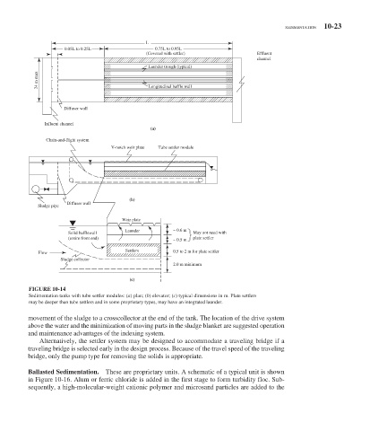
FIGURE 10-14
Sedimentation tanks with tube settler modules: ( a ) plan; ( b ) elevator; ( c ) typical dimensions in m. Plate settlers
may be deeper than tube settlers and in some proprietary types, may have an integrated launder.
movement of the sludge to a crosscollector at the end of the tank. The location of the drive system
above the water and the minimization of moving parts in the sludge blanket are suggested operation
and maintenance advantages of the indexing system.
Alternatively, the settler system may be designed to accommodate a traveling bridge if a
traveling bridge is selected early in the design process. Because of the travel speed of the traveling
bridge, only the pump type for removing the solids is appropriate.
Ballasted Sedimentation. These are proprietary units. A schematic of a typical unit is shown
in Figure 10-16 . Alum or ferric chloride is added in the first stage to form turbidity floc. Sub-
sequently, a high-molecular-weight cationic polymer and microsand particles are added to the