
Page 405 - Water and wastewater engineering
P. 405
10-22 WATER AND WASTEWATER ENGINEERING
C L of chain & tee rails
Opening in floor
Sludge Launder
for drive chain
Stop gates C L of chain & tee rails
Walkway
Effluent
Influent
Equipment C L of chain & tee rails
symmetrical
Sludge Launder
about center line Tank width
C L C L of chain & tee rails
of drive
Diffuser wall (a) Plan view
Tank length
Chain tightener
Effluent weirs
Free board
Max water level
Tank depth Sludge Tank depth Effluent
Influent
Min slope 45 ° Chain for chain-and-flight collector
(b) Profile
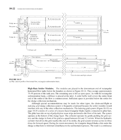
FIGURE 10-13
( a ) Plan and ( b ) profile of horizontal-flow, rectangular sedimentation basin.
High-Rate Settler Modules. The modules are placed in the downstream end of rectangular
horizontal flow tanks below the launders as shown in Figure 10-14 . They occupy approximately
75–95 percent of the tank area. The remaining area is left as open space. As with the rectangular
sedimentation basin, a diffuser is placed at the inlet. A solid baffle wall covers the entire front
end of the settler if the flow is countercurrent. Sufficient space is provided below the settler for
the sludge collection mechanism.
Although special accommodations may be made for other types, the chain-and-flight or
indexing grid sludge collection system is frequently employed because the settler modules would
interfere with any of the other collection mechanisms. The indexing grid system ( Figure 10-15 ) on
page 10-24 consists of a series of concave-faced triangular blades rigidly connected to glide bars.
The glide bars ride on top of polyethylene wear strips anchored to the floor of the tank. The system
operates at the bottom of the sludge layer. The collector operates by gently pushing the grid sys-
tem and the sludge in front of the grid at a speed between 0.6 and 1.2 m/min. When the hydraulic
cylinder that drives the grid reaches the end of its stroke, the grid system reverses at two to three
times the forward speed. During the return movement, the triangular shaped blades slide under the
sludge so that there is minimum disturbance to the sedimentation process. The result is a continuous