
Page 404 - Water and wastewater engineering
P. 404
SEDIMENTATION 10-21
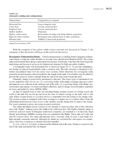
TABLE 10-1
Alternative settling tank configurations
Nomenclature Configuration or comment
Horizontal flow Long rectangular tanks
Center feed Circular, horizontal flow
Peripheral feed Circular, horizontal flow
Upflow clarifiers Proprietary
Upflow, solids contact Recirculation of sludge with sludge blanket, proprietary
High-rate settler modules Rectangular tank, parallel plates or tubes, proprietary
Ballasted sand Addition of microsand, proprietary
Adapted from Kawamura, 2000.
With the exception of the upflow solids contact unit that was discussed in Chapter 7, the
remainder of this discussion will focus on the preferred alternatives.
Rectangular Sedimentation Basins. Current design practice is shifting from rectangular sedimen-
tation basins to high-rate settler modules or, in some cases, dissolved air flotation (DAF). The rectan-
gular sedimentation basin design is presented here because, historically, it has been the most frequently
used design and because it serves as the fundamental structure for high-rate settler modules.
A rectangular basin with horizontal flow is shown in Figure 10-13 . To provide redundancy,
two basins are placed longitudinally with a common wall. The inlet structure is designed to dis-
tribute flocculated water over the entire cross section. Outlet structures for rectangular tanks
generally include launders placed parallel to the length of the tank. Cross baffles may be added to
prevent the return of surface currents from the end of the tank back toward the inlet.
Generally, sludge is removed by mechanical collectors. The major types of mechanical col-
lectors ranked in order of cost are: (1) a traveling bridge with sludge-scraping squeegees and a
mechanical cross collector at the influent end of the tank, (2) a traveling bridge with sludge suc-
tion headers and pumps, (3) chain-and-flight collectors, and (4) sludge suction headers supported
by floats and pulled by wires (MWH, 2005).
As may be impled from its title, the traveling bridge system consists of a bridge across the
width of the tank that travels up and down the tank on wheels resting on the tank wall or side
rails. Either scraper blades or a suction device is suspended from the bridge to the sludge zone.
The suction system is equipped with either a pump or it makes use of a siphon effect from the
differential head between water levels in the clarifier and the sludge line to remove the sludge.
For water treatment systems, the pump system is preferred.
The chain-and-flight system consists of two strands of chain on either side of the collection
area with “flights” running across the width of the collection area. The flights, formerly made of
redwood, and now made of fiberglass reinforced composite, are attached at 3 m intervals. High
density polyethylene (HDPE) wearing shoes are attached to the flights. These ride on T-rails cast
into the concrete floor. The chain and sprocket drive, formerly made of steel, is now made of a
high-strength composite material. Although the chains are corrosion free and require less mainte-
nance, they have a tendency to stretch when first installed.
A cross collector, or hopper, is placed at the influent end of the tank. Sludge is scraped to the
end of the tank and pushed into the hopper.