
Page 399 - Water and wastewater engineering
P. 399
10-16 WATER AND WASTEWATER ENGINEERING
ws
Height of interface H HS HS TS
TS
TS
TS
CS CS CS CS
t 0 t t 1 t t 2 t t 3 t t 4
(a)
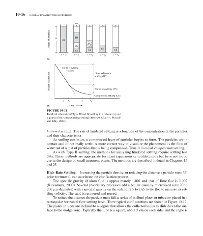
Slope settling
velocity Hindered (zone)
Height of interface settling (HS)
Transition settling (TS)
Compression settling (CS)
t 1 t 2 t 3 t 4
(b) Time
FIGURE 10-11
Idealized schematic of Type III and IV settling in a column ( a ) and
a graph of the corresponding settling curve ( b ). ( Source: Metcalf
and Eddy, 2003.)
hindered settling. The rate of hindered settling is a function of the concentration of the particles
and their characteristics.
As settling continues, a compressed layer of particles begins to form. The particles are in
contact and do not really settle. A more correct way to visualize the phenomena is the flow of
water out of a mat of particles that is being compressed. Thus, it is called compression settling.
As with Type II settling, the methods for analyzing hindered settling require settling test
data. These methods are appropriate for plant expansions or modifications but have not found
use in the design of small treatment plants. The methods are described in detail in Chapters 15
and 25.
High-Rate Settling. Increasing the particle density, or reducing the distance a particle must fall
prior to removal, can accelerate the clarification process.
The specific gravity of alum floc is approximately 1.001 and that of lime floc is 1.002
(Kawamura, 2000). Several proprietary processes add a ballast (usually microsized sand 20 to
200 m diameter) with a specific gravity on the order of 2.5 to 2.65 to the floc to increase its set-
tling velocity. The sand is recovered and reused.
To reduce the distance the particle must fall, a series of inclined plates or tubes are placed in a
.
rectangular horizontal flow settling basin. Three typical configurations are shown in Figure 10-12
The plates or tubes are inclined to a degree that allows the collected solids to slide down the sur-
face to the sludge zone. Typically the tube is a square, about 5 cm on each side, and the angle is