
Page 394 - Water and wastewater engineering
P. 394
SEDIMENTATION 10-11
50% v /2
0
v 0
v /2 Escape
0
50%
Captured
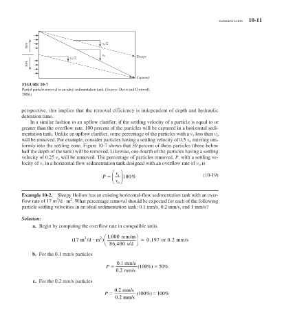
FIGURE 10-7
Partial particle removal in an ideal sedimentation tank. ( Source: Davis and Cornwell,
2008.)
perspective, this implies that the removal efficiency is independent of depth and hydraulic
detention time.
In a similar fashion to an upflow clarifier, if the settling velocity of a particle is equal to or
greater than the overflow rate, 100 percent of the particles will be captured in a horizontal sedi-
mentation tank. Unlike an upflow clarifier, some percentage of the particles with a v s less than v o
will be removed. For example, consider particles having a settling velocity of 0.5 v o entering uni-
formly into the settling zone. Figure 10-7 shows that 50 percent of these particles (those below
half the depth of the tank) will be removed. Likewise, one-fourth of the particles having a settling
velocity of 0.25 v o will be removed. The percentage of particles removed, P, with a settling ve-
locity of v s in a horizontal flow sedimentation tank designed with an overflow rate of v o is
⎛ v ⎞
P ⎜ s ⎟ 100 % (10-19)
⎝ v ⎠
o
Example 10-2. Sleepy Hollow has an existing horizontal-flow sedimentation tank with an over-
3
2
flow rate of 17 m /d · m . What percentage removal should be expected for each of the following
particle settling velocities in an ideal sedimentation tank: 0.1 mm/s, 0.2 mm/s, and 1 mm/s?
Solution:
a. Begin by computing the overflow rate in compatible units.
2 ⎛ 1 000 mm/m⎞
,
3
.
(17 m /dm ) ⎜ ⎝ 86 400 s/d ⎠ ⎟ 0.1197 or 0 2 mm/s
,
b. For the 0.1 mm/s particles
01 . mm/s
P (100 ) %
% 50
02 . mm/s
c. For the 0.2 mm/s particles
02 . mm/s
P ( 100 ) %
% 100
02 . mm/s