
Page 392 - Water and wastewater engineering
P. 392
SEDIMENTATION 10-9
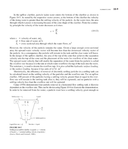
In the upflow clarifier, particle-laden water enters the bottom of the clarifier as shown in
Figure 10-5 . As noted by the respective vector arrows, at the bottom of the clarifier the velocity
of the rising water is greater than the settling velocity of the particle. As the water rises, the area
through which it passes is increasing because of the cone shape of the clarifier. From the continu-
ity principle the velocity of the water decreases as it rises:
Q
v (10-13)
A c
where v velocity of water, m/s
3
Q flow rate of water, m /s
2
A c cross-sectional area through which the water flows, m
However, the velocity of the particle remains the same. Given a large enough cross-sectional
area, the upward water velocity vector will become less than the downward velocity vector of
the particle. As a consequence, the particle will remain in the tank and the clear water will leave.
In the design of the upflow clarifier, the area of the top of the cone that achieves the separation
velocity sets the top of the cone and the placement of the weirs for overflow of the clear water.
The upward water velocity that will enable the separation of the water from the particle is called
the overflow rate because it is the rate at which water overflows the top of the tank into the weirs.
The notation v o is used to denote the overflow rate. It is also called the hydraulic surface loading,
2
3
or the surface loading, because it has units of m /d · m .
Theoretically, the efficiency of removal of discretely settling particles in a settling tank can
be calculated based on the settling velocity of the particles and the overflow rate. For an upflow
clarifier, 100 percent of the particles having a settling velocity greater than or equal to the over-
flow rate will remain in the settling tank (that is, they will be captured), and no particles with a
settling velocity less than the overflow rate will be captured.
Camp (1936) demonstrated that particle removal in a horizontal flow settling tank is likewise
dependent on the overflow rate. This can be shown using Figure 10-6 to illustrate the demonstration.
In order to be removed from the water, a particle must have a settling velocity great enough so
Surface area A Liquid
s
v v v
l 0 s
Q
v A s
0
v l v s
Settled particles
Liquid flow rate Q Particles liquid
FIGURE 10-5
Settling in an upflow clarifier. (Legend: v l velocity
of liquid; v s terminal settling velocity of particle.)
( Source: Davis and Cornwell, 2008.)