
Page 412 - Water and wastewater engineering
P. 412
SEDIMENTATION 10-29
Horizontal-Flow Rectangular Sedimentation Basin Design Criteria
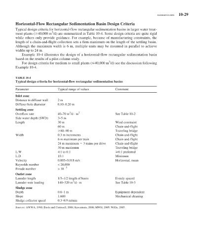
Typical design criteria for horizontal-flow rectangular sedimentation basins in larger water treat-
3
ment plants ( 40,000 m /d) are summarized in Table 10-4 . Some design criteria are quite rigid
while others only provide guidance. For example, because of manufacturing constraints, the
length of a chain-and-flight collection sets a firm maximum on the length of the settling basin.
Although the maximum width is 6 m, multiple units may be mounted in parallel to achieve
widths up to 24 m.
Example 10-4 illustrates the design of a horizontal-flow rectangular sedimentation basin
based on the results of a pilot column study.
3
For design criteria for medium to small plants ( 40,000 m /d) see the discussion following
Example 10-4 .
TABLE 10-4
Typical design criteria for horizontal-flow rectangular sedimentation basins
Parameter Typical range of values Comment
Inlet zone
Distance to diffuser wall 2 m
Diffuser hole diameter 0.10–0.20 m
Settling zone
3
Overflow rate 40–70 m /d · m 2 See Table 10-2
Side water depth (SWD) 3–5 m
Length 30 m Wind constraint
60 m Chain-and-flight
80–90 m Traveling bridge
Width 0.3 m increments Chain-and-flight
6 m maximum per train Chain-and-flight
24 m maximum 3 trains per drive Chain-and-flight
30 m maximum Traveling bridge
L:W 4:1 to 6:1 6:1 preferred
L:D 15:1 Minimum
Velocity 0.005–0.018 m/s Horizontal, mean
Reynolds number < 20,000
5
Froude number > 10
Outlet zone
Launder length 1/3–1/2 length of basin Evenly spaced
3
Launder weir loading 140–320 m /d · m See Table 10-3
Sludge zone
Depth 0.6–1 m Equipment dependent
Slope 1:600 Mechanical cleaning
Sludge collector speed 0.3–0.9 m/min
Sources: AWWA, 1990; Davis and Cornwell, 2008; Kawamura, 2000; MWH, 2005; Willis, 2005.