
Page 429 - Water and wastewater engineering
P. 429
11-2 WATER AND WASTEWATER ENGINEERING
11-1 INTRODUCTION
Settled water turbidity is generally in the range from 1 to 10 NTU with a typical value being
2 NTU. Because these levels of turbidity interfere with the subsequent disinfection processes,
the turbidity must be reduced. The Interim Enhanced Surface Water Treatment Rule (IESWTR)
promulgated by the U.S. Environmental Protection Agency (EPA) requires that the treated water
turbidity level be 0.3 NTU in 95 percent of monthly measurements with no sample to exceed 1
NTU. In order to reduce the turbidity to this level, a filtration process is normally used. The most
common filtration process is granular filtration where the suspended or colloidal impurities are
separated from water by passage through a porous medium. The medium is usually a bed of sand
or other media such as coal, activated carbon, or garnet. In the last two decades, filters composed
of membranes have been employed with increasing frequency. Granular filtration process are the
subject of this chapter. Membrane processes are discussed in Chapter 12.
11-2 AN OVERVIEW OF THE FILTRATION PROCESS
A number of classification systems are used to describe granular filters including media type,
filtration rate, washing technique, and filtration rate control. This discussion is limited to slow
sand, rapid sand, and high-rate filters with either multimedia or deep monomedium the focus
is on rapid sand and high-rate filters. Pressure filters (also called precoat filters) and automatic
backwash filters are not discussed. Discussion of these types of filters may be found in Cleasby
and Logsdon, 1999; Kawamura, 2000; MWH, 2005; Reynolds and Richards, 1996.
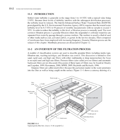
Granular filters are called depth filters because the particulate matter in the water penetrates
into the filter as well as being caught on the surface. Figure 11-1 shows a cutaway drawing of a
Wash trough
Inlet
main Gullet
Wash water
outlet
Surface wash unit
Filter media
Graded gravel
Underdrain blocks
Outlet main
FIGURE 11-1
Typical gravity filter box. ( Source: F. B. Leopold Co.)