
Page 262 - Well Control for Completions and Interventions
P. 262
256 Well Control for Completions and Interventions
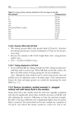
Table 7.3 Casing surface pressure schedule for first two stage of well kill
bbls pumped Casing pressure
0 375 psi
50 330 psi
100 287 psi
150 243 psi
200 199 psi
218 packer fluid to surface 183 psi
250 155 psi
300 111 psi
350 67 psi
400 22 psi
426 0 psi
7.3.8.6 Annulus filled with kill fluid
• The tubing remains filled with annulus fluid (0.52 psi/ft.), therefore
the tubing head pressure remains unchanged at 375 psi (as for the pre-
vious step).
• Because the annulus is full of kill weight fluid, static casing pressure
will be 0 psi.
• 5731 2 (10,300 3 0.5564) 5 0 psi.
7.3.8.7 Tubing displaced to kill fluid
• As the kill fluid fills the tubing through the SSD, tubing head pressure
will drop until it reaches 0 psi. When kill fluid reaches the surface, the
HP at the SSD will be 5731 psi, giving the 231 psi overbalance.
Note: Although the choke should be used to control casing pressure, there will
probably need to be adjustments made to the pump output. Good communications
between the choke and pump operators are essential for maintaining the correct
BHP (Fig. 7.2).
7.3.9 Reverse circulation: worked example 2—plugged
vertical well with heavy fluid in the annulus
Packer fluid left in the annulus when the well was originally completed
will often be significantly denser than would be necessary to kill the well
after depleting the reservoir. Following on from the previous example,
the effect of having a kill brine that is significantly lighter than the packer
fluid is examined. The packer fluid used in this example has a gradient of
0.67 psi/ft. and reflects the density needed to control the well at the