
Page 269 - Well Control for Completions and Interventions
P. 269
Well Kill, Kick Detection, and Well Shut-In 263
1200
Casing pressure
1000
Casing pressure - psi. 800
600
400
200
0
0 100 200 300 400 500 600 700
Volume pumped (bbls)
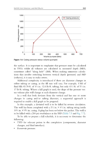
Figure 7.6 Casing pressure versus volume pumped.
the surface. It is important to emphasize that pressure must be calculated
in TVD, whilst all volumes are calculated in measured depth (MD),
sometimes called “along hole” (AH). When making numerous calcula-
tions that involve switching between vertical depth (pressure) and MD
(volume), it is easy to make errors.
Additional complexity is introduced if there are diameter changes in
either tubing or casing, as the fill rate will vary. For example, 1 bbl of
1
1
fluid fills 65.78 ft. of 4/2 in. 12.6 lb/ft. tubing, but only 43.1 ft. of 5/2 in.
17 lb/ft. tubing. Where a kill graph is used, the slope of the pressure ver-
sus volume plot will change at each diameter change.
In a well that both deviates from the vertical and has one or more
changes in casing and/or tubing diameter, a sequential approach is
required to enable a kill graph to be prepared.
In this example, a deviated well is to be killed by reverse circulation.
1
The well has been completed with a 5/2 in. 3 4/2 in. tubing string inside
1
5
3
10/4 in. 3 9/8 in. casing. A plug has been set below the packer. The well is
to be killed with a 200 psi overbalance at the SSD (Table 7.5 and Fig. 7.7).
To be able to prepare a kill schedule, it is necessary to determine the
following:
• TVD for relevant points in the completion (components, diameter
changes, and fluid interface).
• Reservoir pressure.