
Page 270 - Well Control for Completions and Interventions
P. 270
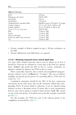
264                                Well Control for Completions and Interventions


          Table 7.5 Well data
          SITP                               2750 psi
          Tubing gas oil contact             3500 ft. MD
          Gas gravity                        0.65 sg
          Oil gradient                       0.35 psi/ft.
          Original packer (annulus) fluid    Inhibited water 0.433 psi/ft. 8.33 ppg
                                               3
          Casing 1 (upper)                   10/4 in. 65.7 lb/ft. 9.560 in. ID
                                              5
          Casing 2 (lower)                   9/8 in. 53.5 lb/ft. 8.958 in. ID
                   1
          5/2 in. 3 4/2 in. cross-over       4800 ft. MD
           1
          SSD                                13,060 ft. MD
          Packer                             13,100 ft. MD
          Plug (in tail-pipe)                13,115 ft. MD
          Reservoir datum (top reservoir)    13,520 ft. MD
          TD                                 14,000 ft. MD


          •  Density (weight) of fluid is required to give a 200 psi overbalance at
             the SSD.
          •  Pressure differential at the SSD before it is opened.


          7.3.10.1 Obtaining measured versus vertical depth data
          For most wells, detailed trajectory data is easy to obtain (or at least it
          should be). Data may be obtained as a hard copy in the form of a spread-
          sheet. Multiple data points list MD in feet or meters, inclination (in
          degrees), azimuth (in degrees) and TVD in feet or meters.
             More commonly, trajectory data is stored and manipulated using pro-
          prietary software such as Halliburton’s “Compass.” The use of software
          simplifies and speeds up the process of converting MD to TVD (and vice
          versa)(Fig. 7.8).
             Completion schematics should list the MD of the key components
          and features in the well. Some, but not all, schematics will list the corre-
          sponding TVDs. If vertical depth is unknown, it can be obtained using
          software or from a deviation survey. If survey data is used, interpolation
          between two survey points is required unless known depth falls exactly
          on one of the data points. A deviation survey for this example is provided
          in Table 7.6.
             For this example, the TVDs for each of the relevant points in the
          completion are provided in Table 7.7.