
Page 140 - Whole Earth Geophysics An Introductory Textbook For Geologists And Geophysicists
P. 140
(V,).
of density
at
of interface
123
velocity
from
acoustic
(h), separating material
(V,)
and
Waveform
Model
seismic velocity
(p,)
in
Graph of change
of density
a)
5.24
Seismic
material
and
FIGURE
depth
(p;)
b)
. (u) YWdag
+7
al
Reflection
Coefficient
O
¢)
-1
4.
Impedance
b) Acoustic
x
Mode!
(Depth)
a)
Sm
P, p,V>, = 1, to p,V, = J, impedance, from I interface in across the Reflection (a).c) acoustic resulting from coefficient impedance change (b). in le AN, b et Seismic Response Reflection Acoustic Model Seismic Signal (Amplitude) Coefficient Impedance Time) Travel (Two-Way a A j A, Q 4 0 1 4 to an (A;).b) The seismic response amplitude certain a w
A FIGURE
& e
Analysis Principles of seis- a of approximately geologic to depends layers of polarity and the on depends
Waveform portion a to encompass responds two amplitude It wave.
And outcrop of sedimentary strata. From compare thus photograph. between the incident p:V;)
Processing, by A. D. Miall, 1984. Reprinted by permission of Springer-Verlag, New York. might together that the reflection ihethod the in __ interface an layers: the of pV expresses the to _ (e,V2 = p:Vs) + (p,V2
Acquisition, scale outcrop layers thin layers the than Coefficient from back impedance l= 5.24) (Fig. interface, relative materials: 1,) (22 ™ 1) + (I,
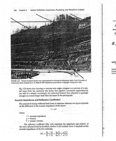
Reflection: seismic trace, superimposed on © in layering numerous wavelength; scale larger Reflection reflected acoustic impedance velocity. coefficient an two of the = rc
Seismic how shows the Note seismic a much a and Impedance of energy the in difference acoustic = density = seismic = reflection from reflected impedance
Chapter5 Portion of typical Sedimentary Basin Analysis, 5.23 Fig. trace. mic of half one on changes amount The the on where: ] p V The wave the acoustic
122 5.23 FIGURE Acoustic