
Page 143 - Whole Earth Geophysics An Introductory Textbook For Geologists And Geophysicists
P. 143
(S) euy jerwsly ABA4-OML
(S) ew JeAel, ABA-OML
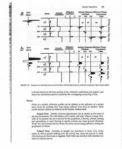
125 Total Seismic Trace Total Selsmic Trace sees Sem trace seismic Noise of result causing vibra- walking the trucks, rattle. sys-
Waveform Selsmic Response (Minimum Phase): 3rd = Seismic Response (Minimum Phase) 3rd —, (b) low frequency input seismic signals. seismic the 5.27b). (Fig. a of interface. the as animals ground vibrations. Cars, noise. to ground electrical with
Seismic Interfaces 2nd + | + Intertaces 2nd {t+ + . coefficients, events deflection the an from once itself. shaken be objects, other Likewise, cause can connecting geophones, causing to the cause interfere
+1 fst Ist +1 reflection overlapping as defined reflected method can and bushes, geophones. streams contribute line, can which
Reflection Coefficient 0 Reflection Coeficient #O interfaces with (a) high frequency and the be seismic (geophones) the cables can survey field
“1 1 “1 lL the of by can energy the trees, by nearby the people the
eee Acdusth Impedance spacing induced flowing also walking a
tic Ge , caused profile than by receivers shakes recorded in shake of near magnetic
several time pattern reflection other Seismic svind are Activities cause
= from the anything that water animals can people
Model AY Model oY Se to interference seismic by natural, cultural, or Noise phenomena. The ground or vibrate. Noise as lines seismic survey.
Response of reflections relative a caused Natural the geophones, rain, and to Cultural well
&
1st 2nd 1st 3rd broad the shows on Noise trace be natural of tions near Wind, geophones as trains, Electrical power of a tems
Input Signal Input Signal 5.27 is Noise can
a b FIGURE
:
TES EN RE EGE! SPT ME mS Baer assy rome x Re ayow ee * e Ri ware ence
(5) oun poansy (s) ours jonny which seis- or the result- acoustic nega- reflecting inter- dis- signal
Analysis . AGM-OML ABM -OML reflection input positive of that the is (Fig. 5.26c). the If three input
Waveform Zero Phase Zero Phase response for reflection coefficient. coefficient, layers. the as is coefficient than greater > 0). The (RC If 5.26b). coefficient signal one than interface. signal), the however,
And Seismic Response Minimum Phase Seismic Response Minimum Phase reflection two the polarity is positive (Fig. reflection input the more is each input the If,
Processing, Zero Phase +1 +41 phase seismic signals. b) Seismic for negative the of of impedance opposite or reflection the reflecting layer be will input signal the <I,), of there When for responses of width the 5.27a). (Fig.
Acquisition, Input Selsmic Signal (‘Pulse’) . Reflection Coefficient (RC>O) Oo “1 ~ootficiont (RC <0) #0 -1 the strength acoustic same the has whether the of coefficient the as is smaller (I, opposite polarity Interfaces the of sum (compared to trace seismic
Reflection: Minimum Phase Acoustic Impedance Increases) I —N imnendence Decreases) ly. zero phase and reflection coefficient. c) Seismic response and wave the in wave depends on impedance reflection polarity same layer the is Several the is apart the on
Seismic (l= pV / («pV minimum incident difference reflected the 5.26a) acoustic the I,), > the reflecting reflection from trace seismic far appear
Input positive of the the on Whether (Fig. the If (1, has of the < 0). The Reflections the sufficiently will
Chapters Model nave 202 Sw Model AY) (2Y,< PY a) 5.26 interface with amplitude depends signal mic negative. above layer reflection impedance (RC tive interface are faces events tinct
tl
124 b Ev AY a FIGURE at ing
{