
Page 141 - Whole Earth Geophysics An Introductory Textbook For Geologists And Geophysicists
P. 141
at (V,). p,V>, A, to an two-
of interface (V,) velocity acoustic 1, to acoustic (Amplitude) Q interface interface travel interface on
123 of density from = Reflection Seismic Response appears at or the the
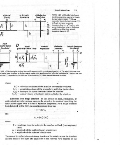
Waveform Model a) (h), separating material seismic velocity and (p,) in p,V, = J, interface in (a).c) resulting from (b). in 4 (A;).b) The seismic response (A,); it interface. layers two the interface. attenuation, convolving of single a (two-way the above depends
Seismic 5.24 and of density Graph of change impedance, from impedance change Reflection Coefficient 0 the “> the below interface the below noise, of result For back and velocity wave
FIGURE depth (p;) material b) across the coefficient 1 amplitude between and the and the as coefficients. has: wave reflected
. (u) YWdag certain to the amplitude of the reflection coefficient interface above layers below and above absence the viewed trace (RC) interface the y seismic wave. of the the
+7
al
Reflection Coefficient O Acoustic Impedance a with thickness (h) and velocity (V,) of the material above the of the above layers In be can reflection seismic 2h/V, = (Aj) i to (input) seismic function a of
¢) -1 4. of the Interface trace of resulting T = A, Tt surface incident reflected thus amplitude
Time) specific waveform coefficient layers of series the is
le Travel signal, scaled impedance of the velocity Single seismic a the 5.25), from the of of the wave The
b) Acoustic Impedance I Model (Two-Way is a input reflection acoustic density seismic from a with (Fig. time amplitude amplitude reflected layer. the
b seismic signal as the the on = RC = l, = P},P2 V2 = arrivals, signal h depth travel = time) I the of depth
x input dependent I,, V,, Reflection seismic seismic at T < A, time of the
Mode! (Depth) 4 a) The has the same waveform (T) where: ; othér input buried and where: The and
a) et Seismic Signal a A j time
Sm 5.25
P, AN, interface way travel
A FIGURE
& e
Analysis Principles of seis- a of approximately geologic to depends layers of polarity and the on depends
Waveform portion a to encompass responds two amplitude It wave.
And outcrop of sedimentary strata. From compare thus photograph. between the incident p:V;)
Processing, by A. D. Miall, 1984. Reprinted by permission of Springer-Verlag, New York. might together that the reflection ihethod the in __ interface an layers: the of pV expresses the to _ (e,V2 = p:Vs) + (p,V2
Acquisition, scale outcrop layers thin layers the than Coefficient from back impedance l= 5.24) (Fig. interface, relative materials: 1,) (22 ™ 1) + (I,
Reflection: seismic trace, superimposed on © in layering numerous wavelength; scale larger Reflection reflected acoustic impedance velocity. coefficient an two of the = rc
Seismic how shows the Note seismic a much a and Impedance of energy the in difference acoustic = density = seismic = reflection from reflected impedance
Chapter5 Portion of typical Sedimentary Basin Analysis, 5.23 Fig. trace. mic of half one on changes amount The the on where: ] p V The wave the acoustic
122 5.23 FIGURE Acoustic