
Page 216 - Whole Earth Geophysics An Introductory Textbook For Geologists And Geophysicists
P. 216
focal
the same
at
is exactly the
view of radiation
for right-lateral, strike-slip fault
arrival
Auxiliary fault
right-
resulted
boundary (Fig. 2.20).
as a
pattern
lower
and
dilatation
the
solu-
the
fault
199
first-motion
San Andreas
(a), plotted
(a), showing that
Foca)
for
the
by
from
fault
the
have
mechanism
information
the
from
encompassed
(c)
compression/dilatation
lefi-lateral fault. d)
Tectonics
on
the
for
of
pattern could
degrees)
solution. c)
Map
of
resulting
reverse)
of the
in
view
solution
occurring along the
of
7.17b).
(a).
regions
indicated
a)
dip
plate
First-motion
information in
interpretation
in
focal
a
Plate
7.15
same as that
fault
mechanism
of
faults depict
mechanism
(in
(Fig.
angle
or
transform
radiation
angles
FIGURE
stations
The
pattern
by
distances
from a
lateral
and
(normal
fault
the
surrounded
b)
7.16c).
Earthquakes
~
the
normal
1)
Compression
a
movement
dip-slip
indicate
that:
make
the
(Fig.
Dilatation
2)
7.18 illustrates
a
see
compression
surface
represents
90°;
for
diagram
would
of
White =
Black =
solutions
equals
sense
the
bird
of the
pattern
on
and
diagram
projections, Fig.
has
mechanism
stations
a
that
angle
portion
fault
opposite
half of the focal sphere
the
dip
at
reverse
inside
arrivals
Focal
of
the
. 4 . A . ee,
the
such
portion
to
the
7.17a);
7.16b).
relates
a
First
©
For
to
for
C=Compression
edges
inside
(Fig.
(Fig.
tion
that
Dilatation
=
D
the indicates diagram the of portion inside the of trend the 3) and planes; ‘auxiliary mechanism focal of examples shows 7.19 Fig. plane. fault earthquake the of strike nor- for faults, auxiliary and earthquake the of sections cross with along solutions, faults. strike-slip and reverse, mal, TE
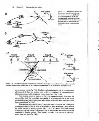
Initial ground motions and Initial the pushes up; the Z-component shows an as a arrival Initial pulls the ground down; the shows a downward first Me Time —=> in (a). by and the actual have focal of view dip-slip be can earth-
7.13 Z-component seismograms for P-wave arriving at a seismic station. (a) compression as a first motion. (b) First Motion b Down 7 First Motion Up 2 First Motion Down 3 a) Waves radiate outward synthesized be compression determine the to could also called are map a have that dilatation the of
FIGURE arrival ground upward dilatation Z-component motion, three stations highlighted in can of 7.15b). uniquely perpendicular fault) dilatation simply and section
fl quadrants (Fig. not are faults cross
Woh 3 . : for the information with does A fault strike-slip and they faults, For 7.15b,d). of compression around a
First Motion Ground Moves fj latation . “\ \, ‘s earthquake occurring on a reverse fault. seismograms first-motion circle, a white, respectively 7.15a Fig. in earthquake. left-lateral, a compression strike-slip (Fig. quadrants sphere)
Seismology S. Up. ff] i \ ON Compression Z-component 7.15a. The stations on and black pattern the caused case this in quadrants of vertical, stations faults), (focal circle 7.16a).
Earthquake -- ren Ground 2 Moves il dilatation. b) The Fig, view in the from by the observed that 7.15c). (Fig. depicting For solutions. seismic at reverse and a drawing (Fig. fault
ene 5 “Co Initial P-wave radiation pattern from an map arrivals represented that fault the (auxiliary fault plane; responsible Diagrams arrivals (normal by and
Chapter7 “—~@=p- Initial Dilatation Down ™~ ff and on shown plotting dilatation Note of nature one been mechanism initial motion visualized quake focus
198 Ground Moves a fl 4 7.14 quadrants of compression the
Focus FIGURE