
Page 100 - Fluid Power Engineering
P. 100
78 Chapter Six
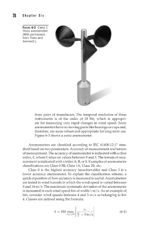
FIGURE 6-2 Class 1
Thies anemometer.
(With permission
from Thies and
Ammonit.)
three pairs of transducers. The temporal resolution of these
instruments is of the order of 20 Hz, which is appropri-
ate for measuring very rapid changes in wind speed. Sonic
anemometers have no moving parts like bearings or cups and,
therefore, are more robust and appropriate for long-term use.
Figure 6-3 shows a sonic anemometer.
1
Anemometers are classified according to IEC 61400-12-1 stan-
dard based on two parameters: Accuracy of measurement and terrain
of measurement. The accuracy of anemometer is indicated with a class
index, k, where k takes on values between 0 and 3. The terrain of mea-
surement is indicated with a letter A, B, or S. Examples of anemometer
classifications are Class 0.5B, Class 1A, Class 2B, etc.
Class 0 is the highest accuracy (unachievable) and Class 3 is a
lower accuracy anemometer. To explain the classification scheme, a
quick exposition of how accuracy is measured is useful. Anemometers
are tested in wind tunnels in which the wind speed is varied between
0 and 16 m/s. The maximum systematic deviation of the anemometer
is measured in each wind speed bin of width 1 m/s. As an example of
bin, consider wind speeds between 4 and 5 m/s as belonging to bin
4. Classes are defined using the formula:
ε i
(6-1)
k = 100 max
U i
2
1≤i≤15 + 5 m/s