
Page 102 - Fluid Power Engineering
P. 102
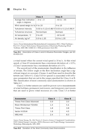
80   Chapter Six


                                  Class A           Class B
               Average flow inclination −3to +3      −15 to +15
                 angle in degrees
               Wind speed range (m/s) 4to16         4to16
               Turbulence intensity  0.03 to 0.12+0.48/V 0.03 to 0.12+0.96/V
               Turbulence structure  Nonisotropic   Isotropic
                            ◦
               Air temperature, C  0to40            −10 to 40
               Air density, kg/m 3  0.9 to 1.35     0.9 to 1.35

              Source: From International Electrotechnical Commission (IEC). Wind Turbines –
              Part 12-1: Power Performance Measurements of Electricity Producing Wind
              Turbines. 2005. IEC 61400-12-1. With permission from IEC.

              TABLE 6-1 Description of Class A and B Influence Parameter Ranges, per IEC
              61400-12-1

              a wind tunnel when the correct wind speed is 10 m/s. At this wind
              speed, a Class 0.5 anemometer has a maximum deviation of ± 0.5%;
              a Class 1 anemometer has a maximum deviation of ± 1%.
                 The second part of the anemometer classification is the influence
              of terrain. The inflow angle or the flow inclination angle has a sig-
              nificant impact on accuracy. Classes A and B are used to describe the
              terrain (see Table 6-1). Class S (S for special) is associated with influ-
              ence parameters that are not in the ranges specified for Class A or B.
              The classification of most commonly used anemometers is shown in
              Table 6-2.
                 Class 2 or better sensors are used for power curve measurements
              of wind turbines, permanent met-towers, and temporary met-towers
              that are used to prove wind resources at a site. Class 1.5 or better


               Anemometer                     Class A       Class B
               Thiess First Class Advanced     0.9            3.0
               Risoe Windsensor P2546A         1.4            5.1
               Thiess First Class              1.8            3.8
               Vector A100LK                   1.8            4.5
               NRG #40                         2.4            8.3

              Source: From Young, M., Met Towers & Sensors–Science & Equipment Considerations,
              DNV Global Energy Concepts, AWEA Resource and Project Energy Assessment
              Workshop, Minneapolis, MN, 2009.
              TABLE 6-2 Deviation of the Most Commonly Used Anemometers