
Page 234 - Fluid Power Engineering
P. 234
Basics of Electricity and Generators 201
y Rotor A Stator
B′ C′
x
Rotating
magnetic
field C B
Stator A′ Air gap
Coils
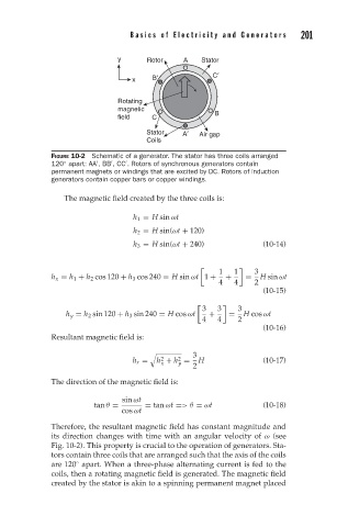
FIGURE 10-2 Schematic of a generator. The stator has three coils arranged
◦
120 apart: AA ,BB ,CC . Rotors of synchronous generators contain
permanent magnets or windings that are excited by DC. Rotors of induction
generators contain copper bars or copper windings.
The magnetic field created by the three coils is:
h 1 = H sin ωt
h 2 = H sin(ωt + 120)
h 3 = H sin(ωt + 240) (10-14)
1 1 3
h x = h 1 + h 2 cos 120 + h 3 cos 240 = H sin ωt 1 + + = H sin ωt
4 4 2
(10-15)
3 3 3
h y = h 2 sin 120 + h 3 sin 240 = H cos ωt + = H cos ωt
4 4 2
(10-16)
Resultant magnetic field is:
3
2 2
h r = h + h = H (10-17)
y
x
2
The direction of the magnetic field is:
sin ωt
tan θ = = tan ωt =>θ = ωt (10-18)
cos ωt
Therefore, the resultant magnetic field has constant magnitude and
its direction changes with time with an angular velocity of ω (see
Fig. 10-2). This property is crucial to the operation of generators. Sta-
tors contain three coils that are arranged such that the axis of the coils
are 120 apart. When a three-phase alternating current is fed to the
◦
coils, then a rotating magnetic field is generated. The magnetic field
created by the stator is akin to a spinning permanent magnet placed