
Page 237 - Fluid Power Engineering
P. 237
204 Chapter Te n
i
L s
Rs
VT
Eg
Rotor
Stator Circuit
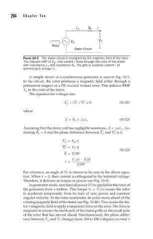
FIGURE 10-3 The stator circuit is energized by the magnetic field of the rotor.
This induces EMF of E g , and current i flows through the coils of the stator
with inductance L s and resistance R s . The grid is supplied current i at
terminal grid voltage V T .
A simple circuit of a synchronous generator is seen in Fig. 10-3.
In the circuit, the rotor produces a magnetic field either through a
permanent magnet or a DC-excited wound rotor. This induces EMF
E g in the coils of the stator.
The equation for voltages are:
−E g + i Z + V T = 0 (10-21)
where
(10-22)
Z = R s + jωL s
Assuming that the stator coil has negligible resistance, Z = jωL s . As-
suming R s = 0 and the phase difference between E g and V T is δ:
E g = E g
δ
V T = V T
0
(10-23)
Z = Z
90 ◦
E f
δ − V t
0
i =
Z
90 ◦
For reference, an angle of V T is chosen to be zero in the above equa-
tion. When δ = 0, then current is orthogonal to the terminal voltage.
Therefore, it delivers no torque or power (see Fig. 10-4).
In generator mode, mechanical power (P) is applied to the rotor of
the generator from a turbine. This torque (τ = P/ω) causes the rotor
to accelerate temporarily from its state of zero power and constant
angular velocity. As the rotor accelerates, its poles move ahead of the
rotating magnetic field of the stator (see Fig. 10-4b). This causes the sta-
tor’s magnetic field to apply a tangential force on the rotor. The force is
magnetic in nature: the north pole of the stator pulls on the south pole
of the rotor that has moved ahead. Simultaneously, the phase differ-
ence between E g and V T changes from 180 to 180-δ degrees as rotor’s