
Page 240 - Fluid Power Engineering
P. 240
Basics of Electricity and Generators 207
Power Stable Unstable
E g >V T
E g =V T
E g <V T
Generator
−180 −150 −120 −90 −60 −30 0 30 60 90 120 150 180
Motor Load angle
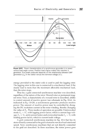
FIGURE 10-5 Power characteristics of a synchronous generator in a power
versus load angle curves. Positive load angles makes this machine a
generator. The power produced depends on the relationship between EMF
generated (E g ) in the stator versus the terminal voltage (V T ).
energy provided to the stator coils is used to pull the lagging rotor.
The lagging rotor in this case is connected to a mechanical load. If the
steady load is more than the maximum allowable mechanical load,
then the rotor stops.
Thus far, a grid connected synchronous machine was described,
regardless of the nature of the rotor: Wound rotor or permanent mag-
net rotor. Next, a characteristic of a wound rotor is described, ability
to control amount of reactive power (see schematic in Fig. 10-6). As
indicated in Eq. (10-28), a synchronous generator produces reactive
power. The amount of reactive power may be controlled by chang-
ing the DC excitation current in the rotor winding, thereby changing
the value of E g . Three modes of operation are possible: Underexcited
mode E g < V T , with lagging power factor, which is current lags volt-
age; E g = V T , unity power factor; and overexcited mode E g > V T with
leading power factor, which is current leads voltage.
A grid connected synchronous machine in Fig. 10-6 that has its
stator directly connected to the grid is forced to run at a fixed rotational
speed. Next, synchronous machines that are not directly connected
to the grid are described. In these machines, the stator power goes