
Page 244 - Fluid Power Engineering
P. 244
Basics of Electricity and Generators 211
ω. A control mechanism that achieves this objective can be designed
to adjust the turbine rotor speed to accomplish optimal power for
different wind speeds.
In addition, such a system can deliver reactive power to the grid;
the amount of reactive power is controlled by using an inductor and
controlling the inverter output voltage (V I ) and its phase angle (δ 1 )
2
relative to the grid. If V I and V T are output voltage of inverter and
terminal grid voltage, then real and reactive power delivered to the
grid is:
3V I V T sin δ 1
P T = 3V T i T cos φ = (10-36)
Z 1
3V 2
3V I V T cos δ 1 T
Q T = 3V T i T sin φ = − (10-37)
Z 1 Z 1
Direct-Drive Synchronous Generator (DDSG)
Enercon popularized this type of generator. Enercon’s E66 1.5 MW
4
generator has 72 poles and produces six-phase power, which is
rectified to DC. This DC current is fed to the rotor and to an inverter.
In order to accommodate the large number of poles, the rotor is large.
As an illustration, consider a DDSG turbine with rotation speed of 10
to 22 rpm. Compared to a 1500 rpm induction generator, the torque
is about 70 times for the same amount of power. The rated torque of
an electrical machine is proportional to the volume of the machine.
Therefore, the volume of DDSG generators is large, which is usually
achieved by increasing the radius. A control mechanism, similar to
the one described for PMSG, can be used to capture optimal power
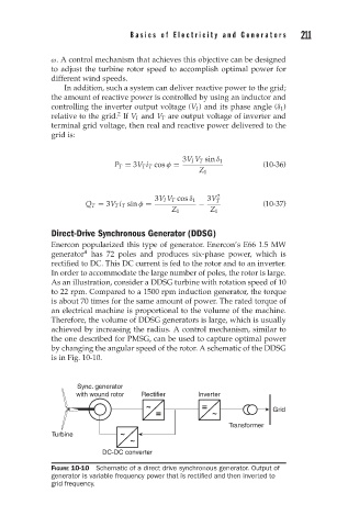
by changing the angular speed of the rotor. A schematic of the DDSG
is in Fig. 10-10.
Sync. generator
with wound rotor Rectifier Inverter
~ = Grid
= ~
Transformer
Turbine ~
~
DC-DC converter
FIGURE 10-10 Schematic of a direct drive synchronous generator. Output of
generator is variable frequency power that is rectified and then inverted to
grid frequency.