
Page 245 - Fluid Power Engineering
P. 245
212 Chapter Te n
Asynchronous Generators
Asynchronous generators are also called induction generators
(Fig. 10-11). The principles are similar to a transformer in which the
primary coils around one side of the core generate magnetic field. This
changing magnetic field produced EMF in the secondary coil on the
other side of the core. Here, energy is transferred from one level of AC
voltage to a different level of AC voltage at the same frequency.
In an induction generator, instead of a solid core, there is an air
gap through which the magnetic field travels. The primary core is in
the stator and the secondary core is in the rotor. In a squirrel cage-
induction generator, the rotor circuit is shorted, so, in an idealized
case, the resistance is zero and, therefore, no electrical load. Like syn-
chronous generator, a rotating magnetic field is created by connecting
the stator to the grid. When the rotational speed of the rotor (ω 0 ) is the
same as the speed of the rotating magnetic field of the stator, then the
relative speed is zero. In this situation, there is no induced EMF in the
rotor because relative to the rotor there is no change in magnetic field.
There is no current in the rotor, and, hence, no force, no torque, and
no power.
When the wind energy is delivering power to the generator, a
torque is delivered to the rotor. Magnitude of the torque is: P/ω. The
torque causes the rotor to accelerate. As the speed of the rotor becomes
ω 1 (>ω 0 ), the conductor in the rotor has a relative velocity (= ω 1 − ω 0 )
with respect to a rotating magnetic field of the stator. This causes EMF
to be induced in the rotor and current starts to flow. The frequency
of the current in the rotor conductor is (ω 0 − ω 1 ) f , where f is the grid
ω 0
frequency. Since the current is flowing in the rotor conductor, which
is immersed in stator’s magnetic field, a force is exerted on the rotor
conductor. This force resists the external torque. The magnitude of
the force is proportional to the current, which is proportional to the
jXs
Rs
T jsXr Rr
i1
is
i2
Eg
jXm Rm E 1 E 2=sE 1 Rx
1:1
Stator Rotor
5
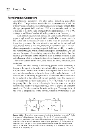
FIGURE 10-11 Equivalent single-phase circuit of an induction generator E g is
the source/grid voltage on the stator; R s , X s , R r , X r are stator side
resistance, reactance, and rotor side resistance and reactance. R m , X m are
resistance because of losses and magnetizing reactance; R x is the external
resistance connected to the rotor to control performance for wound rotors
only. s is the slip. The stator circuit is at frequency of f , where as the rotor
circuit is at frequency sf .